2. WIRING
2-41
MC-3010A/3020D/3030D
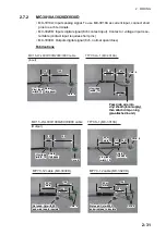
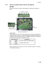
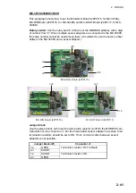
This paragraph shows how to set the MC-ANLG Board (24P0115, for MC-3010A),
MC-DIN Board (24P0116, for MC-3020D) and MC-DOUT Board (24P0117, for MC-
3030D).
Rotary switch:
Use the rotary switch (U18) to set the MODBUS address with a digit
of number from “0”. When multiple sensor adapters are connected to the MC-3000S,
the same number cannot be used among them. (It is allowed to use the same number
between the MC-3000S and a sensor adapter.)
Jumper block
Use the jumper block J25 to set the termination resistor on/off for the MODBUS com-
munication on the connector J1. For the first and last sensor adapter in a series, their
termination resistors should be set to ON. If not, communication between sensor
adapters is not possible.
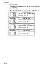
Jumper block J25
Connector J1
1-2
OPEN
Termination resistor: OFF (default)
2-3
SHORT
1-2
SHORT
Termination resistor: ON
2-3
OPEN
U18
U18
U18
J25
J25
J25
J3
J4
J5
MC-ANLG Board (24P0115)
MC-DIN Board (24P0116)
MC-OUT Board (24P0117)
Summary of Contents for FCR-2139S-BB
Page 74: ...2 WIRING 2 48 This page is intentionally left blank ...
Page 136: ...D 1 14 Feb 2011 Y NISHIYAMA ...
Page 137: ...D 2 Y Hatai ...
Page 138: ...May17 07 R Esumi D 3 ...
Page 139: ...13 Feb 2014 H MAKI D 4 ...
Page 140: ...D 5 24 May 2012 Y NISHIYAMA ...
Page 141: ...D 6 24 May 2012 Y NISHIYAMA ...
Page 142: ...D 7 24 May 2012 Y NISHIYAMA ...
Page 143: ...D 8 ...
Page 144: ...D 9 ...
Page 145: ...D 10 ...
Page 148: ...13 Jan 2012 Y NISHIYAMA 西山義浩 D 13 ...
Page 149: ...13 Jan 2012 Y NISHIYAMA D 14 ...
Page 150: ...D 15 ...

