2. WIRING
2-45
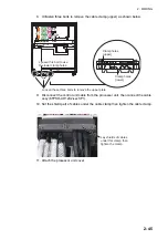
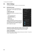
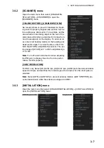
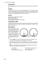
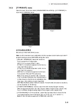
8. Unfasten three bolts to remove the cable clamp (upper) as shown below.
9. Disconnect the control unit cable from the processor unit, then connect the cable
assy (6TPSH-XH12X2-LxxSP1).
10. Set the shield part of cables under the cable clamp then tighten the cable clamp.
11. Attach the processor unit cover.
Loosen these three bolts to remove the upper plate.
Loosen this bolt to use
the lower clamp holes.
Loosen this bolt to use
the lower clamp holes.
Clamp holes
(upper)
Clamp holes
(lower)
J4
J4
J3
J3
J8
J8
J9
J9
J10
J10
J5
J5
J6
J6
J7
J7
J11
J11
J12
J12
J13
J13
J14
J14
Lay shields of cables
under this clamp then
tighten the clamp.
Summary of Contents for FCR-2139S-BB
Page 74: ...2 WIRING 2 48 This page is intentionally left blank ...
Page 136: ...D 1 14 Feb 2011 Y NISHIYAMA ...
Page 137: ...D 2 Y Hatai ...
Page 138: ...May17 07 R Esumi D 3 ...
Page 139: ...13 Feb 2014 H MAKI D 4 ...
Page 140: ...D 5 24 May 2012 Y NISHIYAMA ...
Page 141: ...D 6 24 May 2012 Y NISHIYAMA ...
Page 142: ...D 7 24 May 2012 Y NISHIYAMA ...
Page 143: ...D 8 ...
Page 144: ...D 9 ...
Page 145: ...D 10 ...
Page 148: ...13 Jan 2012 Y NISHIYAMA 西山義浩 D 13 ...
Page 149: ...13 Jan 2012 Y NISHIYAMA D 14 ...
Page 150: ...D 15 ...

