3. SETTING AND ADJUSTMENT
3-7
3.6.2
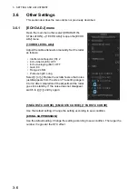
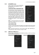
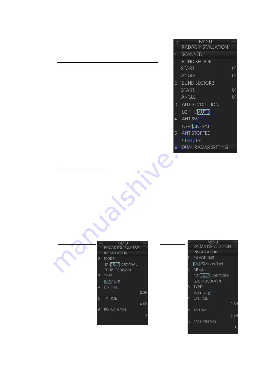
[SCANNER] menu
Open the main menu then select [9 RADAR IN-
STALLATION]
[2 SCANNER] to open the
[SCANNER] menu.
[1 BLIND SECTOR1], [2 BLIND SECTOR2]
Set area(s) where to prevent transmission. Head-
ing must be properly aligned (see section 3.2) be-
fore setting any blind sector. For example, set the
area where an interfering object at the rear of the
antenna would produce a dead sector (area where
no echoes appear) on the display. To enter an ar-
ea, enter start bearing relative to the heading and
dead sector angle. To erase the area, enter 0 for
both the [START] and [ANGLE] sections. The set-
ting range of [START] is 0° to 359° and [ANGLE] is
0° to 180°.
Note:
Turn off a stern blind sector when adjusting
the PM gain, to display the echo from the perfor-
mance monitor properly.
[3 ANT REVOLUTION]
For HSC only. Select [LO] for 36 rpm, [HI] for 42 rpm. [AUTO] sets the normal rotation
speed to 36 rpm and switches the rotation speed to 42 rpm when the short pulse is
selected.
Note:
Select [OFF] at [ANT SW] to prevent antenna rotation. [ANT STOPPED] pre-
vents transmission while the antenna is stopped in STBY.
3.6.3
[INSTALLATION] menu
Open the main menu then select [9 RADAR INSTALLATION]
[3 INSTALLATION] to
open the [INSTALLATION] menu.
IMO-/A-type radars
B-type radar
Summary of Contents for FCR-2139S-BB
Page 74: ...2 WIRING 2 48 This page is intentionally left blank ...
Page 136: ...D 1 14 Feb 2011 Y NISHIYAMA ...
Page 137: ...D 2 Y Hatai ...
Page 138: ...May17 07 R Esumi D 3 ...
Page 139: ...13 Feb 2014 H MAKI D 4 ...
Page 140: ...D 5 24 May 2012 Y NISHIYAMA ...
Page 141: ...D 6 24 May 2012 Y NISHIYAMA ...
Page 142: ...D 7 24 May 2012 Y NISHIYAMA ...
Page 143: ...D 8 ...
Page 144: ...D 9 ...
Page 145: ...D 10 ...
Page 148: ...13 Jan 2012 Y NISHIYAMA 西山義浩 D 13 ...
Page 149: ...13 Jan 2012 Y NISHIYAMA D 14 ...
Page 150: ...D 15 ...

