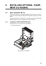
4. INSTALLING OPTIONAL EQUIPMENT (for RADAR)
4-2
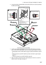
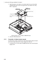
2. Fasten the GYRO CONVERTER board in the radar processor unit with five wash-
er head screws and male connector 231-607/019-FUR (called J602) with two
screws.
Attaching the GYRO CONVERTER board in the radar processor unit
3. Connect the GYRO CONVERTER board and the 03P9342 board with connector
assemblies 03-2088 and 03-2091.
Connector (231)
231-607/019-FUR
1
7
Connector (231)
231-107/026-FUR
11
77
GYRO CONVERTER board
64P1106A
Screw
M3X8 5 pcs
Screw
M2.6X10 2 pcs
Summary of Contents for FCR-2139S-BB
Page 74: ...2 WIRING 2 48 This page is intentionally left blank ...
Page 136: ...D 1 14 Feb 2011 Y NISHIYAMA ...
Page 137: ...D 2 Y Hatai ...
Page 138: ...May17 07 R Esumi D 3 ...
Page 139: ...13 Feb 2014 H MAKI D 4 ...
Page 140: ...D 5 24 May 2012 Y NISHIYAMA ...
Page 141: ...D 6 24 May 2012 Y NISHIYAMA ...
Page 142: ...D 7 24 May 2012 Y NISHIYAMA ...
Page 143: ...D 8 ...
Page 144: ...D 9 ...
Page 145: ...D 10 ...
Page 148: ...13 Jan 2012 Y NISHIYAMA 西山義浩 D 13 ...
Page 149: ...13 Jan 2012 Y NISHIYAMA D 14 ...
Page 150: ...D 15 ...


