4. INSTALLING OPTIONAL EQUIPMENT (for RADAR)
4-11
4.2.3
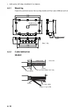
Connection
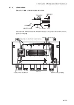
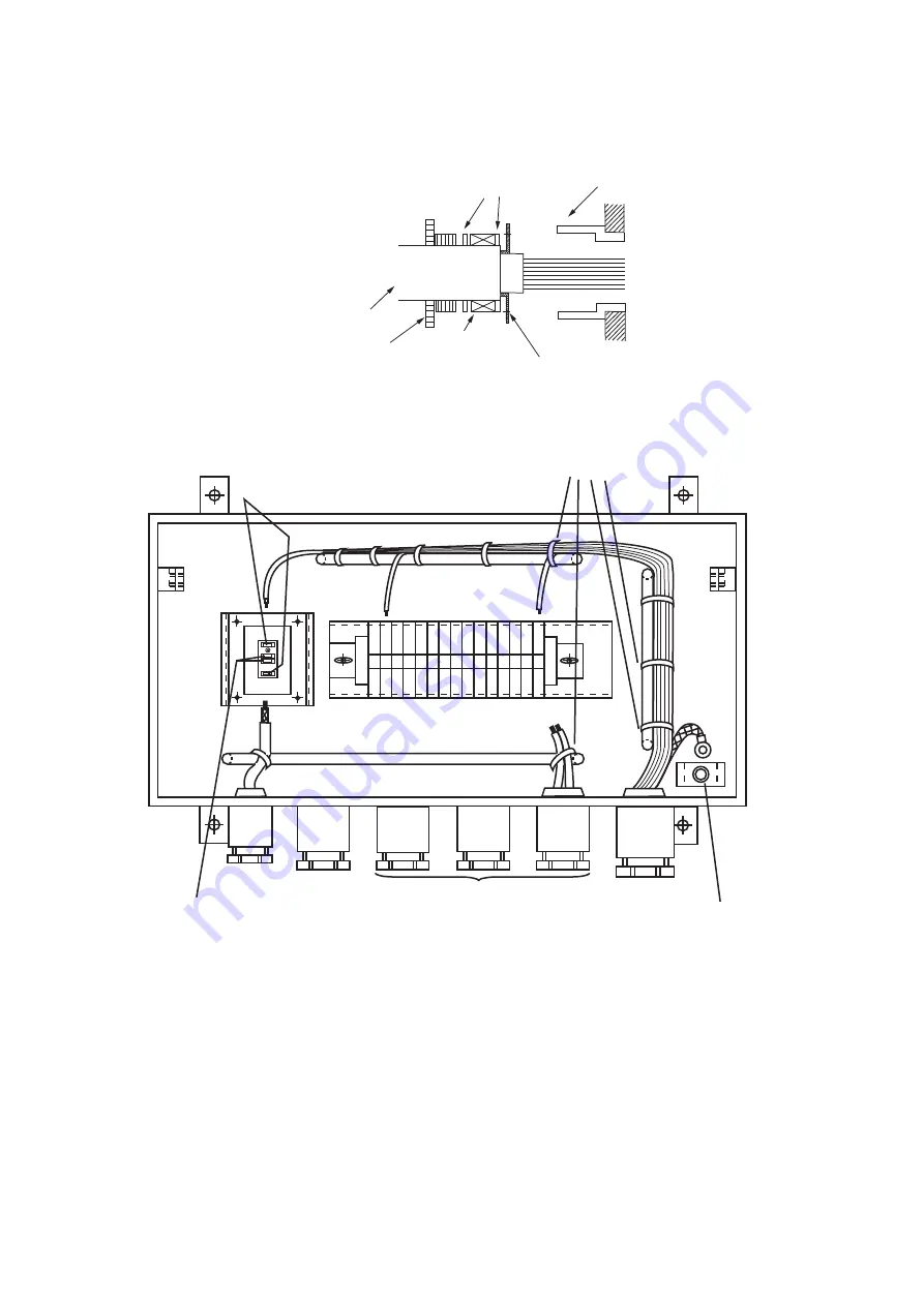
Insert each cable to the cable gland as follows.
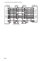
Connect each cable cores to the terminal board, referring to the interconnection dia-
gram on next page.
Flat washer
Cable gland
Vinyl sheath
Clamping gland
Gasket
Cut and trim armor.
15 14 13 12 11 10 9 8 7 6 5 4 3 2 1
RG12/UY
RG-12/UY
TTYCY-4
DPYCY-6
RW-9600
Connect inner conductors.
M8 screw for grounding
Clamp outer conductor of coaxial cables.
Fix wires with cable-tie.
Summary of Contents for FCR-2139S-BB
Page 74: ...2 WIRING 2 48 This page is intentionally left blank ...
Page 136: ...D 1 14 Feb 2011 Y NISHIYAMA ...
Page 137: ...D 2 Y Hatai ...
Page 138: ...May17 07 R Esumi D 3 ...
Page 139: ...13 Feb 2014 H MAKI D 4 ...
Page 140: ...D 5 24 May 2012 Y NISHIYAMA ...
Page 141: ...D 6 24 May 2012 Y NISHIYAMA ...
Page 142: ...D 7 24 May 2012 Y NISHIYAMA ...
Page 143: ...D 8 ...
Page 144: ...D 9 ...
Page 145: ...D 10 ...
Page 148: ...13 Jan 2012 Y NISHIYAMA 西山義浩 D 13 ...
Page 149: ...13 Jan 2012 Y NISHIYAMA D 14 ...
Page 150: ...D 15 ...

