2. WIRING
2-6
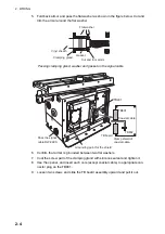
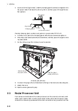
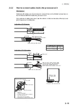
4. As shown in the figure below, slide the clamping gland, washers and gasket onto
the power cable. Fold back the armor by 5mm, and then pass it through the two
flat washers.
Passing clamping gland, washers and gasket on power cable TPYCY-2.5
5. Coat the screw part of the clamping gland with silicone sealant and tighten it.
6. Pass the power cable behind the terminal block, and then pass it through the lock-
ing wire saddle.
7. Fix the crimp-on-lug FV2-4 (blue) to each conductor.
Antenna unit, left view
8. Connect crimp-lug to the terminal block referring to the interconnection diagram.
9. Attach the cover.
10. Seal the cable gland with putty.
2.3
Radar Processor Unit
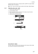
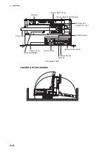
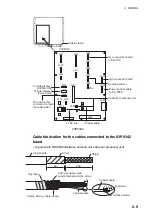
Four cables are terminated at the radar processor unit: the antenna unit cable, LAN
cable, power switch cable, and the power cable. Cables other than the power cable
come with a connector pre-attached to them for connection to the processor unit. Fab-
Gasket
Vinyl sheath
Clamping gland
Flat washer
Cut and trim armor.
Terminal board
for power cable
Pass the power
supply cable here.
Summary of Contents for FCR-2139S-BB
Page 74: ...2 WIRING 2 48 This page is intentionally left blank ...
Page 136: ...D 1 14 Feb 2011 Y NISHIYAMA ...
Page 137: ...D 2 Y Hatai ...
Page 138: ...May17 07 R Esumi D 3 ...
Page 139: ...13 Feb 2014 H MAKI D 4 ...
Page 140: ...D 5 24 May 2012 Y NISHIYAMA ...
Page 141: ...D 6 24 May 2012 Y NISHIYAMA ...
Page 142: ...D 7 24 May 2012 Y NISHIYAMA ...
Page 143: ...D 8 ...
Page 144: ...D 9 ...
Page 145: ...D 10 ...
Page 148: ...13 Jan 2012 Y NISHIYAMA 西山義浩 D 13 ...
Page 149: ...13 Jan 2012 Y NISHIYAMA D 14 ...
Page 150: ...D 15 ...

