1. MOUNTING
2
1.2
Control Unit
1.2.1
Installation considerations
The control unit is designed to be mounted on a tabletop. When selecting a mounting
location, keep in mind the following points:
• Locate the unit where shock and vibration are minimal.
• Leave sufficient space around the unit for maintenance and servicing.
• Locate the unit with consideration for cable length.
• Keep the compass safe distances shown on page i.
Note:
The ground terminal is attached to the bottom of the unit. Connect a ground wire
(IV-1.25 sq, local supply) to the terminal before installing the unit.
1.2.2
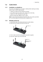
Mounting procedure
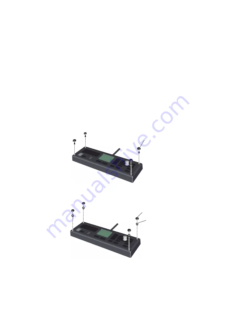
1) Drill four pilot holes in the tabletop referring to the outline drawing.
2) Remove the four cosmetic caps from the control unit.
3) Fix the control unit with four self-tapping screws (
4x20, supplied).
4) Re-set the cosmetic caps to the screw holes.
Cosmetic cap
Self-tapping
screw
Cosmetic cap
Summary of Contents for FCV-1900/B/G
Page 46: ...D 1 14 Apr 2015 H MAKI...
Page 47: ...D 2 15 Apr 2015 H MAKI...
Page 48: ...D 3 15 Jan 2015 H MAKI...
Page 50: ......
Page 51: ......

