2. WIRING
16
2.5
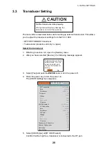
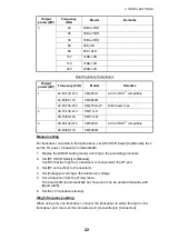
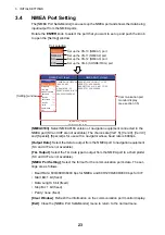
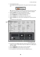
Ethernet HUB
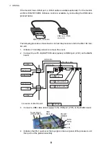
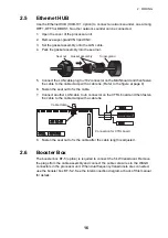
Use the Ethernet HUB (HUB-101, option) to connect a network sounder, one among
DFF1, DFF3 or BBDS1. No other network sounder can be connected.
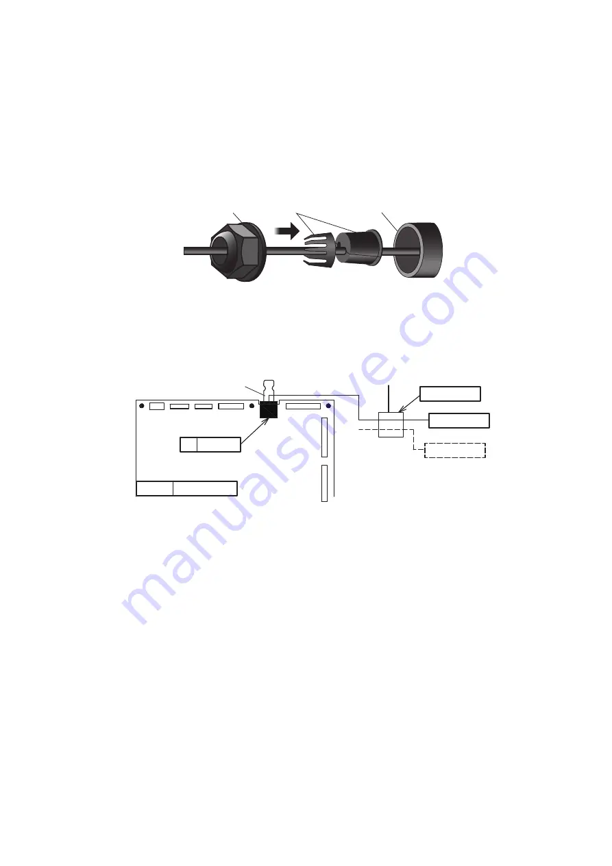
1. Open the cover of the processor unit.
2. Remove super-gland CN3 and CN4.
3. Set the gasket assembly onto the LAN cable.
4. Pack the gasket assembly into the seal nut.
5. Connect the LAN cable plug to J102 connector on the MAIN board and then fasten
the cable to the cable clamp with a cable tie. (Refer to the figure at page 9)
6. Fasten the seal nut to fix the cable.
7. Connect another LAN cable to J4 connector on the CTRL board and then fasten
the cable to the cable clamp with a cable tie.
8. Fasten the seal nut to fix the cable after the cable length is adjusted.
2.6
Booster Box
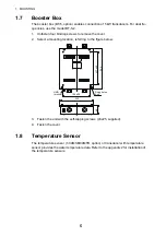
The booster box BT-5 (option) is required to connect the 5 kW transducer. Remove
the plugs from the cable assembly and connect the cable core wires to the WAGO
connectors in the processor unit. When dual frequency transducers are connected,
use the booster box BT-5-2. See the interconnection diagram at back of this manual
for details.
Super-gland
Seal nut
Gasket assembly
USB
USB
J4
J4 RJ-45
RJ-45
NETWORK
NETWORK
CTRL
CTRL
02P6392
02P6392
CN-4
CN-4
Connection for CTRL board
Cable clamp
Summary of Contents for FCV-1900/B/G
Page 46: ...D 1 14 Apr 2015 H MAKI...
Page 47: ...D 2 15 Apr 2015 H MAKI...
Page 48: ...D 3 15 Jan 2015 H MAKI...
Page 50: ......
Page 51: ......

