2. WIRING
12
2.2.3
Transducer
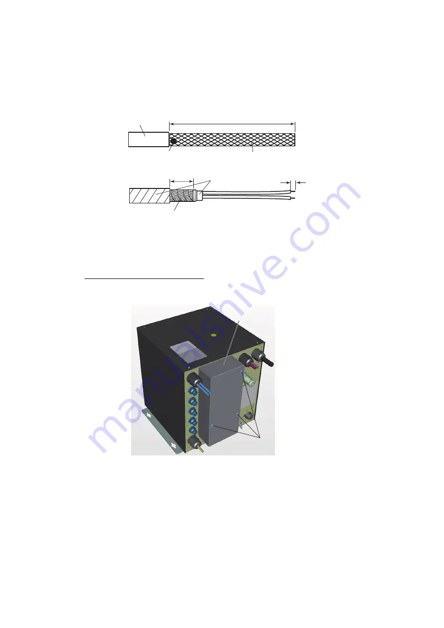
Lay the transducer cable well away from power cables to prevent interference. Con-
nect the cable to the transducer port (for high frequency and/or low frequency) on the
processor unit. Fabricate the cables as shown below.
Note:
Only use the specified optional cables when extending the transducer cable.
Note:
If the transducer cable label interferes with installation, remove the label. (Do
not remove the warranty label from Airmar transducers.) Record the cable assembly
series number then store it for reference.
Transducer cable connection
1. Unfasten three binding screws to remove the connector cover.
2. Disconnect the WAGO connector (CN-2) on the right side of the connector panel.
Braided shield
Vinyl tape
Sheath
Wrap the braided shield around the sheath.
Clamp here with the metal fixture.
Pull the cores out from shield
and remove cushioning materials.
㻢
100
㻞㻜
Binding screws (3 pcs.)
Connector cover
Summary of Contents for FCV-1900
Page 55: ...D 1 14 A pr 2015 H M A KI...
Page 56: ...D 2 15 A pr 2015 H M A KI...
Page 57: ...D 3 15 Jan 2015 H M AKI...
Page 58: ...D 4 5 Jun 2015 H MAKI...
Page 60: ...4 Jun 2015 H MAKI D 6...
Page 61: ...4 Jun 2015 H MAKI D 7...


