2. WIRING
2-7
2.2.1
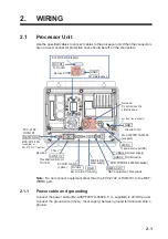
Power cable and grounding
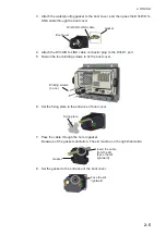
Connect the plug of power cable (MJ-A3SPF0013-035C, 3.5m) to the 24VDC port.
This unit should be grounded to prevent mutual interference. Connect a copper strap
(WEA-1004, 1.2m, supplied) between this unit and the ship’s ground. The length of the
ground strap should be as short as possible.
2.2.2
Transducer cable
Prepare the following for installation
• Cable cutting knife
• Wire cutter
• Cable stripper (AWG25 equivalent)
• Vinyl tape or plastic tube for insulation
• Phillips head screw driver
How to connect the transducer cable
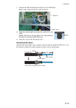
1. Fabricate the cable end as follows.
Note:
To avoid interference, do not change the specified length of fabrication.
2. Unfasten six screws to remove the cover from the processor unit.
CAUTIO
CAUTION
Do not shorten the transducer cable.
Shortening the cable may affect the mea-
surement function’s accuracy. To extend
the distance between the transducer and
processor unit, adjust from the LAN cable
length between processor unit and trans-
ceiver unit.
Unit: mm
Drain wire
(4 lines)
Drain wire
(4 lines)
Terminal lag
(FV2-M4)
Terminal lag
(FV2-M4)
×4 sets
×4 sets
Shield
Shield
Wind the vinyl tape (width: 30mm)
110
Sheath
6-7
Vinyl tape or plastic tube for insulation.
Summary of Contents for FCV-2100
Page 6: ...EQUIPMENT LISTS iv This page is intentionally left blank...
Page 14: ...1 MOUNTING 1 8 This page is intentionally left blank...
Page 46: ...3 INITIAL SETTINGS 3 18 This page is intentionally left blank...
Page 52: ...16 Nov 2015 H MAKI 16 Nov 2015 H MAKI...
Page 53: ...17 Nov 2015 H MAKI 17 Nov 2015 H MAKI...
Page 54: ...26 Feb 2016 H MAKI 26 Feb 2016 H MAKI...
Page 55: ...17 Nov 2011 Y NISHIYAMA 17 Nov 2011 Y NISHIYAMA...
Page 56: ...17 Nov 2011 Y NISHIYAMA 17 Nov 2011 Y NISHIYAMA...
Page 57: ...17 Nov 2011 Y NISHIYAMA 17 Nov 2011 Y NISHIYAMA...
Page 58: ...8 Mar 2016 H MAKI...

