1. MOUNTING
1-7
1.3
Control Unit
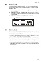
The control unit can be installed on a desktop. The control unit should be mounted
within five meters from the processor unit since the length of the cable connecting
them is five meters.
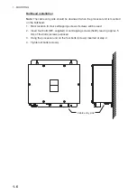
1. Drill four mounting holes of 5 mm diameter referring to the outline drawing at the
back of this manual.
2. Fix the control unit with four self-tapping screws (
I
4) from the top of the control
unit. The M4 screws with a sufficient length for the thickness of the tabletop should
be provided locally.
3. Attach four cosmetic caps to the fixing holes on the control unit.
1.4
Monitor Unit
The system is designed with the MU-190V (local supply) in mind. The output video sig-
nal is in portrait format. For configurations with monitors other than the MU-190V, con-
sider the following points at installation:
• For monitors other than the MU-190V, brightness cannot be adjusted from the menu
or the control unit. Adjust brightness at the monitor itself.
• The output video signal from the FR-1908V-BB/FR-1918V-BB cannot be flipped up-
side-down. For this reason, when installing a landscape monitor select a location
that allows the monitor to be installed after rotating the monitor 90 degrees clock-
wise.
• When using a landscape monitor which has been rotated, the viewing orientation
angles change. This can cause the colors of echoes, etc to change, depending on
the viewing angle.
Fixing hole
Summary of Contents for FR-1908V-BB
Page 2: ...Installation Manual This page is intentionally left blank...
Page 6: ...EQUIPMENT LISTS iv This page is intentionally left blank...
Page 14: ...1 MOUNTING 1 8 This page is intentionally left blank...
Page 30: ...3 ADJUSTMENTS 3 8 This page is intentionally left blank...
Page 40: ...11 Dec 2018 H MAKI D 1...
Page 41: ...D 2 2 Nov 2017 H MAKI...
Page 42: ...D 3 2 Nov 2017 H MAKI...

