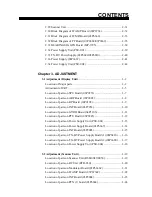
CONTENTS
Chapter1. GENERAL
1.1Outline ............................................................................................. 1-1
1.2 Boards & Major Components .......................................................... 1-2
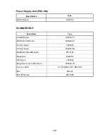
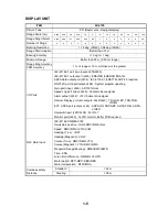
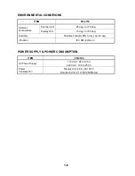
1.3 Specifications .................................................................................. 1-4
Chapter 2. BLOCK DESCRIPTION
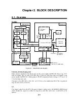
2.1 Overview......................................................................................... 2-1
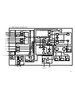
2.2 Block Diagram of Display Unit ....................................................... 2-2
2.3 Function of Each Board (Display Unit)............................................ 2-4
2.4 Start-up Sequence............................................................................ 2-6
2.5 Block Diagram of SPU Board.......................................................... 2-8
2.6 Video Signal Flow ........................................................................... 2-9
2.7 Block Diagram of SPU Board (Video Amplifier)............................. 2-10
2.8 Auto Tuning Function...................................................................... 2-11
2.9 Tuning Indication ............................................................................ 2-12
2.10 Manual Tuning .............................................................................. 2-12
2.11 Tuning Circuit ............................................................................... 2-12
2.12 Echo averaging (EAV 1/2/3) .......................................................... 2-13
2.13 Echo Stretch 1/2 and Enhanced video ............................................ 2-14
2.14 Memories & Memory Frame Priority............................................. 2-15
2.15 Antenna on/off Control.................................................................. 2-16
2.16 Check of ARP and RP board Connection....................................... 2-17
2.17 ARP-23 vs. ARP-26 ...................................................................... 2-17
2.18 Simple ARPA block diagram ......................................................... 2-18
2.19 ARPA block diagram..................................................................... 2-19
2.20 ARPA target acquisition and Tracking ........................................... 2-20
2.21 ARPA Land Discrimination ........................................................... 2-20
2.22 ARPA INITIAL SETTING MENU................................................ 2-21
2.23 Block Diagram of RP Board .......................................................... 2-24
2.24 INPUT/OUTPUT Data on INT Board (03P9252) .......................... 2-25
2.25 Sentences Receivable at J450 on INT-9170 ................................... 2-26
2.26 Radar and ARPA output signal from INT-9170.............................. 2-27
2.27 Monitor signal from J449............................................................... 2-28
2.28 Power Supply Circuit (AC)............................................................ 2-29
Summary of Contents for FR-2155
Page 1: ...MARINE RADAR MODEL FR 2155 PRINTED IN JAPAN...
Page 3: ......
Page 4: ......
Page 5: ......
Page 65: ...3 9 Location of Parts on RP Board 14P0298 CR1 S1 Battery BT1 Flash ROM U3...
Page 80: ...3 24 Location of Parts on PFN 1 board 03P6668...
Page 86: ......
Page 107: ......
Page 108: ......
Page 109: ......
Page 110: ......
Page 111: ......
Page 112: ......
Page 113: ......
Page 114: ......
Page 115: ......
Page 116: ......
Page 117: ......
Page 118: ......
Page 119: ......
Page 121: ......
Page 122: ......
Page 123: ......
Page 124: ......
Page 125: ......
Page 126: ......
Page 127: ......
Page 128: ......
Page 129: ......
Page 130: ......
Page 131: ......
Page 132: ......
Page 133: ......
Page 134: ......
Page 135: ......
Page 136: ......
Page 137: ......
Page 138: ......
Page 139: ......
Page 140: ......
Page 141: ......
Page 142: ......
Page 143: ......
Page 144: ......
Page 145: ......
Page 146: ......
Page 147: ......
Page 148: ......
Page 149: ......
Page 150: ......
Page 151: ......
Page 152: ......


