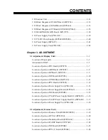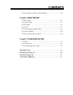
CONTENTS
2.29 Scanner Unit .............................................................................2-31
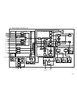
2.30 Block Diagram of IF AMP Board (03P6734) ............................2-32
2.31 Block Diagram of IF MD Board (03P6666) ..............................2-33
2.32 Block Diagram of PF Board (03P6668/03P6669) ......................2-35
2.33 BEARING SIG GEN Board (MP-3795)....................................2-38
2.34 Power Supply Unit (PSU-001) ..................................................2-39
2.35 TX-HV Power Supply (03P6680/03P6810)...............................2-40
2.36 Power Supply (03P6667)...........................................................2-41
2.34 Power Supply Unit (PSU-004) ..................................................2-42
Chapter 3. ADJUSTMENT
3.1 Adjustment (Display Unit)
.............................................................3-2
Location of Major parts ....................................................................3-2
Adjustment of CRT...........................................................................3-5
Location of parts on SPU Board (03P9253) ......................................3-7
Location of parts on ARP Board (18P9002) ......................................3-8
Location of parts on RP Board (14P0298).........................................3-9
Location of parts on INT Board (03P9252) .......................................3-10
Location of parts on GYRO Board (64P1106)...................................3-11
Location of parts on PTU Board (03P9245) ......................................3-12
Location of parts on Power Supply Unit (PSU-001)..........................3-13
Location of parts on Power Supply Board (03P6667)........................3-14
Location of parts on INT Board (03P9003) .......................................3-15
Location of parts on TX-HV Power Supply Board (1)(03P6810) ......3-16
Location of parts on TX-HV Power Supply Board (2)(03P6680) ......3-17
Location of parts on Power Supply Unit (PSU-004)..........................3-18
3.2 Adjustment (Scanner Unit)
............................................................3-19
Location of parts on Scanner Unit (RSB-0049/0050) ........................3-19
Location of parts on RF Unit (RTR-030)...........................................3-20
Location of parts on Modulator Board (03P6666C)...........................3-21
Location of parts on IF AMP Board (03P6734C) ..............................3-22
Location of parts on INT Board (03P9004) .......................................3-23
Location of parts on PFN (1) board (03P6668)..................................3-24
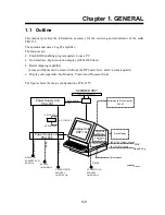
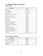
Summary of Contents for FR-2155
Page 1: ...MARINE RADAR MODEL FR 2155 PRINTED IN JAPAN...
Page 3: ......
Page 4: ......
Page 5: ......
Page 65: ...3 9 Location of Parts on RP Board 14P0298 CR1 S1 Battery BT1 Flash ROM U3...
Page 80: ...3 24 Location of Parts on PFN 1 board 03P6668...
Page 86: ......
Page 107: ......
Page 108: ......
Page 109: ......
Page 110: ......
Page 111: ......
Page 112: ......
Page 113: ......
Page 114: ......
Page 115: ......
Page 116: ......
Page 117: ......
Page 118: ......
Page 119: ......
Page 121: ......
Page 122: ......
Page 123: ......
Page 124: ......
Page 125: ......
Page 126: ......
Page 127: ......
Page 128: ......
Page 129: ......
Page 130: ......
Page 131: ......
Page 132: ......
Page 133: ......
Page 134: ......
Page 135: ......
Page 136: ......
Page 137: ......
Page 138: ......
Page 139: ......
Page 140: ......
Page 141: ......
Page 142: ......
Page 143: ......
Page 144: ......
Page 145: ......
Page 146: ......
Page 147: ......
Page 148: ......
Page 149: ......
Page 150: ......
Page 151: ......
Page 152: ......


