1-5
Mounting the scanner unit
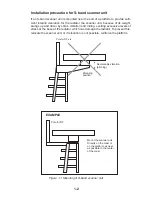
1. Referring to the scanner outline drawing, drill four bolt holes (15 mm dia.) in the
radar mast platform or the deck.
2. Place the corrosion-proof rubber mat (supplied) on the mounting platform.
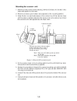
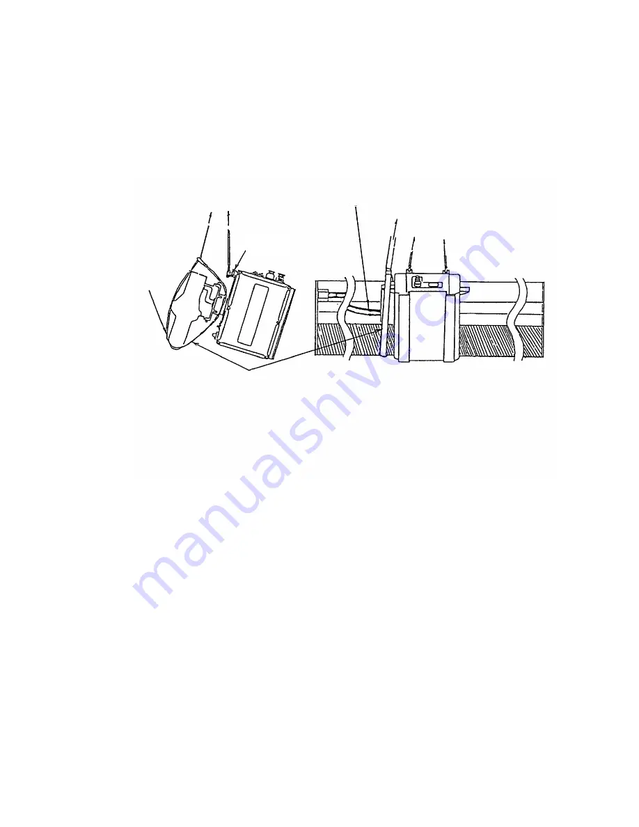
3. Using the two L-angle metal plates on the scanner top, lift the scanner base
with the antenna radiator and place the scanner unit on the rubber mat. Orient
the scanner so its cable glands face the ship’s stern.
Feeder waveguide
Note 2
L-angle
metal plate
Place the rope around scanner radiator
(feeder waveguide side) to prevent
scanner from rotating when lifting
the scanner base.
Note 1: Take care not to damage scanner exterior
by the rope.
Note 2: Tensile load should not be applied
to scanner radiator.
Note 1
Figure 1-3 How to lift the scanner unit
4. Fix the scanner base to the mounting platform with four M12x60 hex bolts,
nuts, washers and seal washers (supplied).
5. Arrange the grounding terminal at the nearest grounding spot with the M6x25
hex bolt, nut and washers (supplied). Then, fix a ground wire (RW-4747, 320
mm long) to the terminal.
6. Connect the other end of the ground wire to the ground terminal of the scanner
unit.
7. Coat grounding terminal and fixing bolts on the scanner unit with silicone seal-
ant (supplied).
Summary of Contents for FR-2165DS
Page 1: ...MARINE RADAR MODEL FR 2165DS...
Page 61: ......
Page 62: ......
Page 63: ......
Page 64: ......
Page 65: ......
Page 66: ......
Page 67: ......
Page 68: ......
Page 69: ......
Page 70: ......
Page 71: ......
Page 72: ......
Page 73: ......
Page 74: ......
Page 75: ......
Page 76: ......
Page 77: ......
Page 78: ......
Page 79: ......
Page 80: ......
Page 81: ......
Page 82: ......
Page 83: ......
Page 84: ......
Page 85: ......
Page 86: ......
Page 87: ......
Page 88: ......
Page 89: ......
Page 90: ......
Page 91: ......
Page 92: ......

