1-9
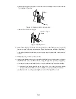
b) While pushing the stopper, set the catch on the display unit in the hole at the
front edge of the stay.
Catch
Stopper
Stay
Figure 1-8 Setting catch to hole in stay
c) Release hand from stopper.
Release stopper;
fix stay.
Figure 1-9 Stay fixed
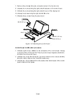
6. Fasten the display unit to the mounting location at front fixing holes (2 points)
with M10 bolts, nuts and flat washers, using the pipe box spanner (supplied).
You cannot fasten the display unit at the rear fixing holes while the monitor is
raised.
7. Retract the stay and lower the monitor.
8. Fasten the display unit to the mounting locations at rear fixing holes (2 points)
with M10 bolts, nuts and flat washers, using the pipe box spanner (supplied).
The rear left hole is hid under the PTU cover. Remove the cover as follows:
(1) Unfasten five M3x8 screws at the top of the PTU cover and two M4x8
screws at the front of the cover to slide the cover toward the front side.
(2) Remove the cover by grasping the knob on the top of the cover.
Summary of Contents for FR-2165DS
Page 1: ...MARINE RADAR MODEL FR 2165DS...
Page 61: ......
Page 62: ......
Page 63: ......
Page 64: ......
Page 65: ......
Page 66: ......
Page 67: ......
Page 68: ......
Page 69: ......
Page 70: ......
Page 71: ......
Page 72: ......
Page 73: ......
Page 74: ......
Page 75: ......
Page 76: ......
Page 77: ......
Page 78: ......
Page 79: ......
Page 80: ......
Page 81: ......
Page 82: ......
Page 83: ......
Page 84: ......
Page 85: ......
Page 86: ......
Page 87: ......
Page 88: ......
Page 89: ......
Page 90: ......
Page 91: ......
Page 92: ......


