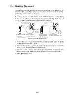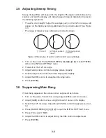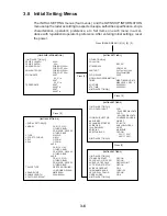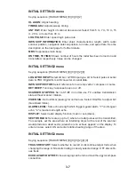
4-8
ARP board adjustment
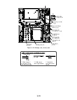
1. Turn the GAIN, A/C SEA and A/C RAIN controls fully counterclockwise, and
then transmit on the 12 nm range.
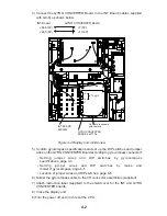
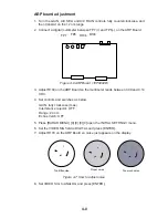
2. Connect a digital multimeter between TP7(+) and TP6(-) on the ARP Board.
TP7
TP6
R104
R103
Figure 4-6 ARP Board (18P9002B)
3. Adjust R104 on the ARP Board so the multimeter reads between 0.09 and 0.14
VDC.
4. Set controls and switches as below.
GAIN: fully clockwise (max.)
Interference rejector: OFF
Range: 24 nm
Echo stretch: OFF
5. Press [RADAR MENU] [0] [0] [0] [0] open the INITIAL SETTING3 menu.
6. Set the VIDEO SIG field to DIGITAL and press [ENTER].
7. Adjust R103 on the ARP Board so noise just appears on the display.
Too little noise
Proper noise
Too much noise
Figure 4-7 How to adjust noise
8. Set VIDEO SIG to ANALOG and press [ENTER].
Summary of Contents for FR-2165DS
Page 1: ...MARINE RADAR MODEL FR 2165DS...
Page 61: ......
Page 62: ......
Page 63: ......
Page 64: ......
Page 65: ......
Page 66: ......
Page 67: ......
Page 68: ......
Page 69: ......
Page 70: ......
Page 71: ......
Page 72: ......
Page 73: ......
Page 74: ......
Page 75: ......
Page 76: ......
Page 77: ......
Page 78: ......
Page 79: ......
Page 80: ......
Page 81: ......
Page 82: ......
Page 83: ......
Page 84: ......
Page 85: ......
Page 86: ......
Page 87: ......
Page 88: ......
Page 89: ......
Page 90: ......
Page 91: ......
Page 92: ......

