4-12
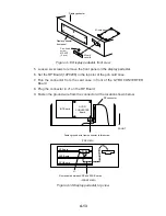
10.Fasten the front panel on the display pedestal.
11. Retract the stay to close the display unit.
12.Fasten the right arm cover.
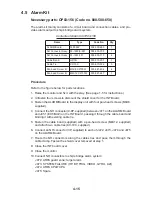
Separate type control head
Necessary parts: RP-26-Z-2E (Code no. 008-491-400)
e
m
a
N
e
p
y
T
y
t
Q
.
o
N
e
d
o
C
.
y
s
s
A
e
s
a
C
d
r
a
C
–
1
–
d
r
a
o
B
P
R
8
9
2
0
P
4
1
1
0
4
6
-
7
8
4
-
8
0
0
B
w
e
r
c
S
d
a
e
H
n
a
P
W
0
0
7
2
C
8
x
4
M
1
5
4
4
-
1
8
8
-
0
0
0
B
w
e
r
c
S
d
a
e
H
n
a
P
W
0
0
7
2
C
8
x
3
M
2
4
0
4
-
1
8
8
-
0
0
0
A
w
e
r
c
S
d
a
e
H
n
a
P
W
0
0
7
2
C
5
x
6
.
2
M
2
3
7
9
-
0
0
8
-
0
0
0
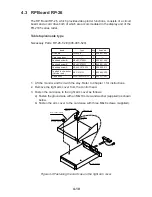
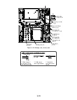
1. Lift the monitor. See Chapter 1 for instructions.
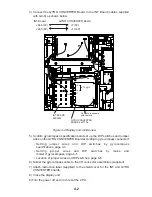
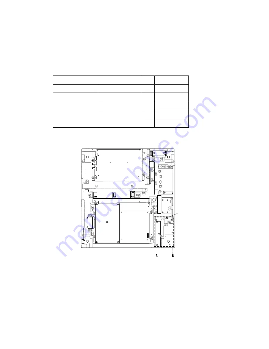
2. Fasten the mounting base with one M4 x 8 screw as below.
Fasten with
M4X8 screw.
Fasten with M3X8
screws (2 pcs.)
Figure 4-12 Display unit, inside view
3. Fix the mounting base to front panel with two M3 x 8 screws.
4. Set the M-card case lid to the hole in the front panel and fix with two M2.6 x 5
screws.
Summary of Contents for FR-2165DS
Page 1: ...MARINE RADAR MODEL FR 2165DS...
Page 61: ......
Page 62: ......
Page 63: ......
Page 64: ......
Page 65: ......
Page 66: ......
Page 67: ......
Page 68: ......
Page 69: ......
Page 70: ......
Page 71: ......
Page 72: ......
Page 73: ......
Page 74: ......
Page 75: ......
Page 76: ......
Page 77: ......
Page 78: ......
Page 79: ......
Page 80: ......
Page 81: ......
Page 82: ......
Page 83: ......
Page 84: ......
Page 85: ......
Page 86: ......
Page 87: ......
Page 88: ......
Page 89: ......
Page 90: ......
Page 91: ......
Page 92: ......

