


1. OPERATIONAL
OVERVIEW
1-4
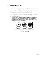
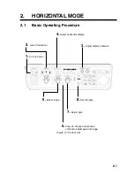
1.5 Control
Panel
Dimmer
The dimmer for the control panel may be adjusted on the DISPLAY SETTING
menu as below.
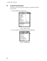
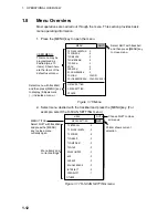
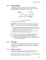
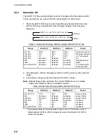
1. Press the [MENU] key to open the menu.
MENU
QUIT
H-SCAN SETTING...
V-SCAN SETTING...
OTHERS...
TX PULSE LENGTH-H : 9
TX POWER-H
: 9
TVG-NEAR-H
: 0
TVG-MEDIUM-H
: 0
TVG-FAR-H
: 0
AGC-H
: 0
2ND AGC-H
: 0
ECHO AVERAGE-H
: 0
COLOR-H
: COLOR 1
COLOR RESPONSE-H : COLOR CURVE 3
Figure 1-3 Menu (default)
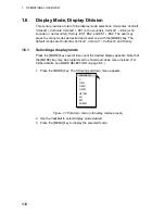
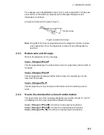
2. Use the trackball to select OTHERS and press the [MENU] key.
ES1 SETTING...
ES2 SETTING...
ERASE MARKS...
DISPLAY SETTING...
FISH ALARM & AUDIO...
PRESET, MEMORY CARD...
INITIAL SETTING...
OTHERS
MENU
QUIT
QUIT
Figure 1-4 OTHERS menu
Summary of Contents for FSV-24
Page 1: ...COLOR SCANNING SONAR FSV 24 ...
Page 12: ...This page is intentionally left blank ...
Page 112: ...This page is intentionally left blank ...
Page 126: ...This page is intentionally left blank ...
Page 144: ...This page is intentionally left blank ...
Page 162: ...This page is intentionally left blank ...


