2. HORIZONTAL MODE
2-8
2.4.5
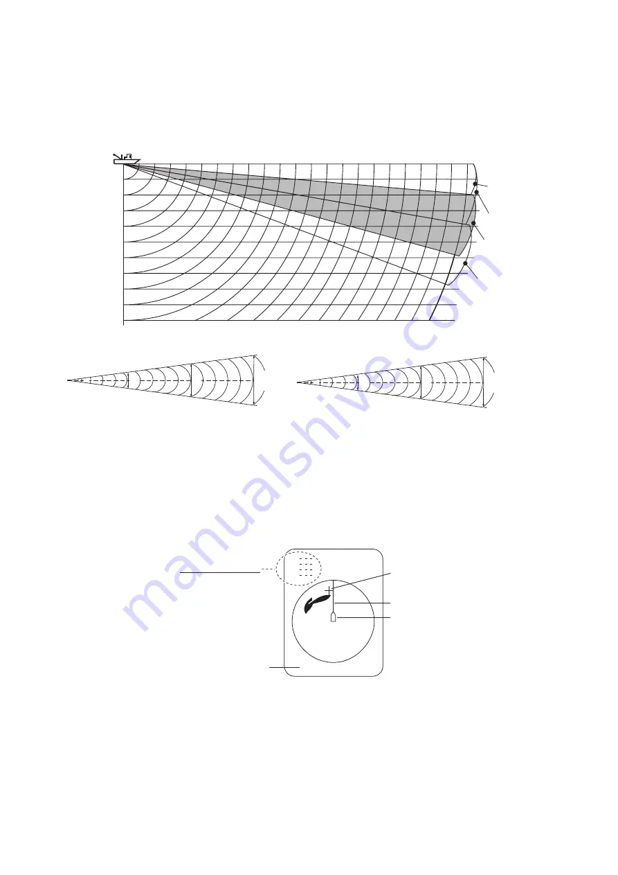
Suitable tilt angle
The figure below illustrates the relationship among tilt angle, depth and detection
range. Refer to it to find out the suitable tilt angle for a given depth/detection range.
2.5
How to Measure Range and Bearing to a Target
Operate the trackball to place the cursor on the target you want to measure the range
and bearing. The range, bearing and depth to the target appear at the upper left corner
of the screen.
Note 1:
Trackball position may also be shown in latitude and longitude. For further de-
tails, see page 6-12.
Note 2:
The bearing display is available in four formats. See page 6-12.
Vertical width of sonar beam
Depth (m)
Tilt angle setting: relationship between tilt angle and detection range
Tilt 0
°
(0°-5°)
Tilt 5
°
(0°-10.5°)
Tilt 15
°
(9.5°-20.5°)
Tilt 15
°
(4.5°-15.5°)
In grey
Range(m)
100
(200)
200
(400)
300
(600)
400
(800)
20(40)
40(80)
60(120)
80(160)
100(200)
200(400)
10
°
17 m
17 m
100 m
300 m
200 m
35 m
35 m
52 m
52 m
11
°
19 m
19 m
100 m
300 m
200 m
39 m
39 m
58 m
58 m
Vertical beam 10°
Vertical beam 11°
Cursor
TRACKBALL DATA
Slant range
Horizontal range
Depth
B Relative or
True bearing
Heading line
Own ship mark
Cursor L/L position
B
34°56.789N
123°45.678E
Summary of Contents for FSV-2S
Page 1: ...COLOR SCANNING SONAR FSV 25 FSV 25S OPERATOR S MANUAL www furuno com Model ...
Page 14: ...SYSTEM CONFIGURATION xii This page is intentionally left blank ...
Page 74: ...2 HORIZONTAL MODE 2 44 This page is intentionally left blank ...
Page 92: ...4 NUMERIC GRAPHIC DATA DISPLAY 4 4 This page is intentionally left blank ...


