

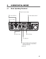


2. HORIZONTAL MODE
2-9
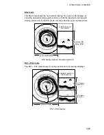
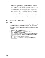
2.4.3
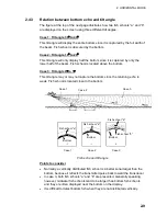
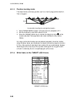
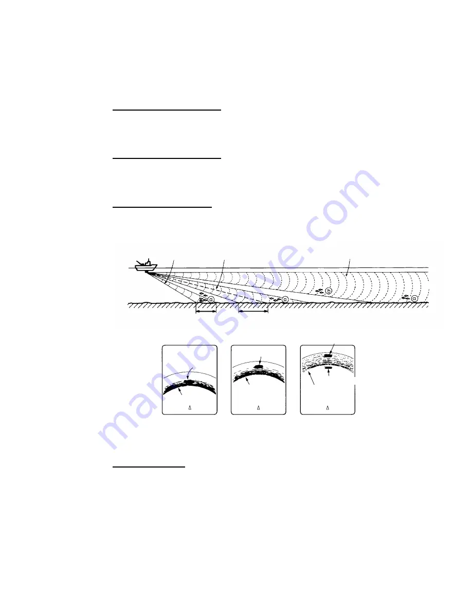
Relation between bottom echo and tilt angle
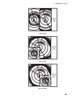
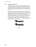
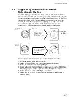
The figure at the top of the next page illustrates how two fish schools “a” and “b”
are displayed on the screen using three different tilt angles.
Case 1: Tilt angle 30
°
to 40
°
This tilt angle will display the entire bottom since it is captured by the full width of
the beam. Fish school is obscured by the bottom.
Case 2: Tilt angle 10
°
to 20
°
This tilt angle will only display half the bottom since it is captured by only the
lower half of the beam. Fish school is located above the bottom.
Case 3: Tilt angle 0
°
to 5
°
This tilt angle may or may not capture the bottom since the returning echo is
weak. Fish school is located close to the bottom.
Case 1
Case 2
Case 3
Case 1
Fish school "a"
Bottom
Fish school "a"
Fish school "a"
Case 2
Case 3
Bottom
Bottom
Fish school "b"
Fish echo and tilt angle
Points to consider
•
Normally, a vertically distributed fish school is a better sonar target than the
bottom, because it reflects the transmitted pulse back toward the transducer.
•
In case 3, both fish schools “a” and “b” are presented. Generally speaking,
however, midwater fish schools tend to be larger than bottom fish schools
and they are often displayed near the bottom on the display.
•
It is difficult to detect bottom fish when they are not distributed vertically.
Summary of Contents for FSV-30
Page 1: ...COLOR SCANNING SONAR FSV 30 ...
Page 14: ...This page is intentionally left blank ...
Page 30: ...1 OPERATIONAL OVERVIEW 1 16 This page is intentionally left blank ...
Page 80: ...2 HORIZONTAL MODE 2 50 The page is intentionally left blank ...
Page 100: ...3 VERTICAL MODE 3 20 The page is intentionally left blank ...
Page 122: ...5 6 This page is intentionally left blank ...
Page 136: ...7 10 This page is intentionally left blank ...
Page 152: ...8 OTHERS MENU 8 16 This page is intentionally left blank ...
Page 170: ...10 MAINTENANCE TROUBLESHOOTING 10 14 This page is intentionally left blank ...
Page 174: ...SP 4 This page is intentionally left blank ...
Page 182: ...ORIGINAL SETTING AP 8 New Original setting ...
Page 183: ...ORIGINAL SETTING AP 9 ...
Page 184: ...ORIGINAL SETTING AP 10 ...
Page 185: ...ORIGINAL SETTING AP 11 Color setting ...
Page 186: ...ORIGINAL SETTING AP 12 Color Response Curve setting ...


