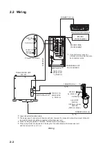


2-2
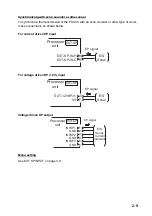
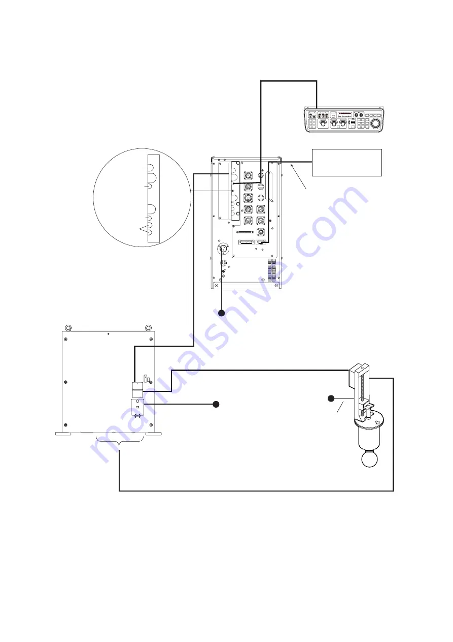
2.2 Wiring
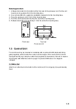
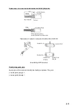
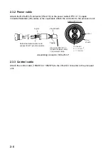
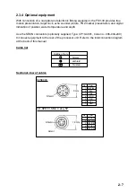
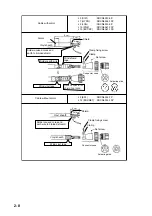
Monitor
(Local supply)
CONTROL UNIT FSV-3001
PROCESSOR UNIT
FSV-3002/3002S
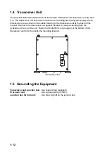
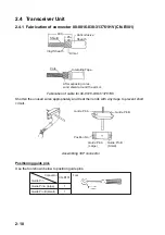
TRANSCEIVER UNIT
FSV-301
HULL UNIT
FSV-303
(1200 mm stroke)
FSV-304
(1600 mm stroke)
10S1258-1
Monitor cable
(Local supply)
10S2223 (14.6 m)
10S2078 (8 m)
100/110/115/
220/230 VAC
1
φ
, 50/60 Hz
*1
*1: If connector may loosen by
vibration monitor cable may also
be connected inside.
Processor unit clamp
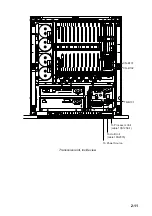
Transceiver
unit
Control unit
Control unit
External
monitor
220 VAC
3
φ
, 50/60 Hz
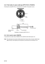
10S2077 (10 m)
DPYCY-1.5 *2
TPYCY-4 *2
*3
*2: Japan Industrial Standard cable
*3: The same type of connector is fitted at each end, however the connector where the amount of sheath
removed is greater should be connected to the transceiver unit.
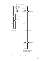
*4: When running the cables of 10S2078, 10S2223 refer to next page.
*5: When using cable for extension kit, the length of the cable between the transceiver unit
and the hull unit is 5 m or 10 m.
*4 *5
*4 *5
FSV-30
100/110/115/
220/230 VAC
1
φ
, 50/60 Hz
DPYCYS-2.5 *2
Wiring
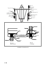
Summary of Contents for FSV-30
Page 56: ...3 16 This page intentionally left blank ...
Page 60: ...4 4 This page intentionally left blank ...
Page 68: ...D 1 ...
Page 69: ...D 2 ...
Page 70: ...D 3 ...
Page 71: ...Y Hatai D 4 ...
Page 72: ...Y Hatai D 5 ...
Page 73: ...Takahashi T Y Hatai D 6 ...
Page 74: ...Takahashi T Y Hatai D 7 ...
Page 75: ...Y Hatai D 8 ...
Page 76: ...D 9 ...
Page 77: ...D 10 ...


