background image

23/Apr/2013

 Y.NISHIYAMA

D-6

Summary of Contents for FSV-35

Page 1: ...1 13 1 7 Grounding the Equipment 1 13 1 8 Attachment Flange option 1 13 1 9 Attachment Kit option 1 14 2 WIRING 2 1 2 1 How to Use the Crimping Tool Pin Extractor 2 1 2 2 How to Connect Units 2 2 2 3 Processor Unit 2 3 2 4 IF Unit 2 6 2 5 Control Unit and Remote Controller 2 9 2 6 Transceiver Unit 2 11 2 7 Transducer Cable Extension Kit 2 14 2 8 Control Box of Hull Unit 2 15 2 9 Input Voltage and ...

Page 2: ... is elemental chlorine free FURUNO Authorized Distributor Dealer 9 52 Ashihara cho Nishinomiya 662 8580 JAPAN A JUL 2012 Printed in Japan All rights reserved C2 MAR 24 2015 Pub No IME 13330 C2 ETMI FSV 35 35S 0 0 0 1 7 5 7 9 1 1 2 ...

Page 3: ...fter the power is turned off Improper handling can result in electrical shock Turn off power at the switchboard before starting the installation Electrical shock or fire can result if the the power is left on Do not install the equipment where it may get wet from rain or water splash Water can cause fire or electrical shock or damage the equipment Be sure no water leaks in at the hull unit Water l...

Page 4: ...the transducer is projected or being raised or lowered is as below to prevent damage to the transducer Projected Raising Lowering 1200 mm stroke Max 18 kn Max 15 kn 1600 mm stroke Max 15 kn Max 12 kn Ground the equipment to prevent electrical shock and mutual interference 1 45 m Processor Unit Control Unit FSV 8501 Standard compass Steering compass 0 90 m 0 35 m 0 30 m IF Unit 0 90 m 0 55m Sub Con...

Page 5: ...evice mouse etc Junction Box FI 5002 NMEA IEC 61162 1 device NMEA IEC 61162 1 device Speaker Sub Control Unit FSV 853 Remote Controller FSV 854 220 VAC 3φ 50 60 Hz Hull Unit Remote Controller FSV 854 Optional equipment Control Unit FSV 8501 Type Stroke FSV 303 䇭1200 mm FSV 304 䇭1600 mm FUSE MAIN SW CHARGE OV ERR BV ERR Extension Kit FSV 305 5 or FSV 305 15 Incl Junction Box Transceiver Unit FSV 35...

Page 6: ... 921 360 1 For Hull Unit Name Type Code No Remarks Control Unit FSV 8501 With 5 m or 10 m cable Sub Control Unit FSV 853 000 019 212 Inst Mat CP10 07501 Rectifier RU 1746B 2 000 030 439 Remote Controller FSV 854 000 017 128 Inst Mat CP10 07401 Junction Box FI 5002 000 010 765 For CANbus NMEA 0183 Attachment Kit OP10 24 006 943 530 For 1600 m stroke Attachment Flange OP10 27 000 067 050 For 1200 m ...

Page 7: ...off the keel If the hull unit can not be installed on the keel the center of the retraction tank should be within 600 mm from the keel to prevent a rolling effect For large ship with deep draft the hull unit can be installed at the bow Select a place where the hull bottom is flat and the draft is sufficiently deep Normal ly the transducer should protrude at least 500 mm beyond the keel to minimize...

Page 8: ...ture around the unit will be below 0 C provide the sonar compartment with a heater to keep the temperature above 0 C Note After you mount the hull unit be sure to install anti vibration stays referring to page 1 5 Compartment 600 24 1300 52 650 26 1000 40 ...

Page 9: ...ct of air foam is minimized because the transducer fully protrudes in water Guideline for the installation of the retraction tank Install if possible the tank on the keel where the tank can be most firmly fixed Install the reinforcement ribs as near as possible to the top of the retraction tank allowing space for tightening of nuts and bolts Fit a doubling plate a plate added to another to give ex...

Page 10: ...llowing points as below and place the hull unit on the tank Clean the flange platform Wipe the undersurface of the hull unit flange with clean waste cloths Keep O ring in its groove 4 Coat the threads of the bolts with a slight amount of lithium grease to prevent scorching Insert the bolts with washers from the retraction tank flange and then put the flat washers and spring washers in this order f...

Page 11: ... be done to prevent damage to the transducer Do not install the stays on a crossbeam on the overhead Vibration resistance effect is reduced since vibration is applied to the stays as rotation force Install them horizon tally Hex nut Spring washer Flat washer Bow mark HULL UNIT FLANGE O ring TANK FLANGE Flat washer Hex bolt Spring washer Flat washer Retraction Tank Bow Bow side 17 places O ring Hex...

Page 12: ... hull unit against vibration by extending stays to prevent the dam age to the transducer from the vibration WRONG INSTALLATION METHOD Stay fixed to crossbeam on overhead CORRECT INSTALLATION METHOD Stay installed horizontally Stay Eye bolt HULL UNIT 90 ...

Page 13: ...ienced on the ship If necessary reinforce the mounting location Determine the mounting location considering the length of these cables Signal ca ble from the transceiver unit control cable from the control unit Leave sufficient space on the sides of the unit to facilitate maintenance Also leave a foot or so of service loop in cables for servicing or easy removal of connectors See the outline drawi...

Page 14: ...crews 6x30 supplied at the top two screw holes leaving approx 5 mm of the screws exposed 3 Hang the processor unit on the two screws inserted at step 2 4 Insert two self tapping screws at the bottom of the unit 5 Tighten all screws Note The processor unit must be installed on the bulkhead with the following direc tion Self tapping screw 6x30 4 pcs UP OK NG ...

Page 15: ...ss safe distance see the Safety Instructions to prevent inter ference to a magnetic compass 1 3 1 Control Unit FSV 8501 Desktop installation with KB fixture 1 Fasten the KB fixture to the selected location with four self tapping screws M5x20 2 Connect a ground wire 1 25 sq local supply between the ground terminal at the bottom of the unit and ship s ground 3 Set the unit on top of the KB fixture a...

Page 16: ...the keyboard fixture to the bottom of the unit with the screws M4x12 supplied 2 Attach rubber feet 2 pcs to the bottom of the unit 3 Fix the unit to the mounting location with self tapping screws local supply Desktop installation no keyboard fixture 1 Drill four mounting holes of 5 mm diameter referring to the outline drawing at the back of this manual 2 Fix the unit with four screws M4 from under...

Page 17: ...ransceiver Unit Select a mounting location considering that the effective length of the cable between the transceiver unit and the hull unit is 5 m standard The transceiver unit should be fixed to a mounting base shipyard supply whose dimensions are as shown in the out line drawing at the back of this manual Reinforce the transceiver unit against vibration by stays extending from the eye bolts on ...

Page 18: ...ion Kit Type FSV 305 15 Code No 000 067 073 Install the unit between the hull unit and transceiver unit Fasten the unit to the mount ing location with four M6 bolts Name Type Code No Qty Remarks Junction box FSV 305 000 067 074 1 Cable assy 10S2240 000 148 369 03 1 set 5 m 10 pcs Cable assy 10S2144 000 145 360 1 12 9 m Name Type Code No Qty Remarks Junction box FSV 305 000 067 074 1 Cable assy 10S...

Page 19: ...moistened waste cloths Coat O ring and O ring groove with lithium grease 2 Place the O ring in position on the retraction tank flange 3 Coat the threads of the bolts with a slight amount of lithium grease to prevent scorching 4 Fix the attachment flange to the retraction tank with flat washers spring washers and hex nuts To install the attachment flange and hull unit see section 1 1 3 Unit Ground ...

Page 20: ...e tank flange 3 Position the hull unit so that the bow mark inscribed on its flange points toward the ship s bow Note that heading adjustment in the monitor is required if the bow mark does not physically face the ship s bow 4 Confirm the following points as below and place the hull unit on the tank Clean the flange platform Wipe the undersurface of the hull unit flange with clean waste cloths Kee...

Page 21: ...s in this order from above Fasten bolts with nuts Hex nut Spring washer Insulation gasket Insulation gasket 2 Flat washer Hex nut Spring washer Flat washer O ring Insulation gasket Insulation gasket 2 Flat washer Hex bolt Hex nut Spring washer Flat washer O ring Insulation gasket Insulation gasket 2 Hex bolt RETRACTION TANK Hull unit flange Bow side 17 locations O ring Flat washer Spring washer He...

Page 22: ...1 HOW TO INSTALL THE SYSTEM 1 16 This page is intentionally left blank ...

Page 23: ...chet releases The wire should be placed deep enough into the contact pin so that its end comes in con tact with the stopper plate of the crimping tool 4 With crimping completed pull the wire while holding the contact pin to make sure that the wire is held firmly by the contact pin 2 1 2 How to use the pin extractor If a contact pin is inserted into an incorrect hole on the connector body remove it...

Page 24: ...ter should be connected to the transceiver unit 2 The details of the cable is shown below 3 When using cable for extension kit the length of the cable between the transceiver unit and the hull unit is 10 m or 20 m HULL UNIT FSV 303 1200 mm stroke FSV 304 1600 mm stroke 10S2223 effective length 5 m 10 pcs 10S2078 8m 220 VAC 3φ 50 60Hz TPYCY 4 1 2 3 2 3 100 110 115 220 230 VAC 1φ 50 60Hz DPYCYS 2 5 ...

Page 25: ...top terminal bottom terminal 3 Close the power terminal cover Transceiver Unit FSV 351 Ship s ground Ground wire IV 8sq 12 24 VDC DPYC 6 External speaker for PC w amp less than 5W 10S2383 3 m FR FTPC CY within 100 m IF Unit FSV 8502 External Monitor SXGA DVI D D SINGLELINK 5 m or 10 m IF Unit FSV 8502 10S1050 3 m Sub control unit FSV 853 option USB cable 47 3 7 20 1 20 5 5 8 to 12 Sheath Armor Cut...

Page 26: ...8 1 WHT ORG 2 ORG 3 WHT GRN 4 BLU 5 WHT BLU 6 GRN 7 WHT BRN 8 BRN WHT ORG 1 ORG 2 WHT GRN 3 BLU 4 WHT BLU 5 GRN 6 WHT BRN 7 BRN 8 Expose inner vinyl sheath Crose cable Straight cable Remove the outer sheath by approx 25 mm Be careful not to damage inner shield and cores Fold back the shield wrap it onto the outer sheath and cut it leaving 9 mm 1 2 3 25mm approx 9mm 4 5 6 approx 9mm approx 11mm Dra...

Page 27: ...164 049 10 1 20 m 1 5C2V 3C2V T 30M 000 164 050 10 30 m 1 5C2V 3C2V T 70M 000 164 051 10 70 m Connector assy BNCX5 DSUB15 L400 000 159 595 01 2 BNC connector BNC P 3 000 500 396 6 For 3C 2V BNC P 1 5V CR DDK 4 Recommended DVI adapter AD DV01 Sanwa Supply 1 Recommended Gender converter adapter AD D15FTDVM Elecom 1 Recommended D sub 15 pin female Analog monitor local supply Processor Unit FSV 3503 F...

Page 28: ...alent cable Connection point Cable type See 1 below See 2 below Remarks Ext KP JIS cable 400 mm 100 mm FURUNO cable 400 mm 120 mm Gyro JIS cable 400 mm 100 mm FURUNO cable 400 mm 100 mm Transceiver Unit FURUNO cable 400 mm 100 mm Standard supply CIF1 JIS cable 400 mm 100 mm FURUNO cable 400 mm 100 mm CIF2 JIS cable 400 mm 120 mm FURUNO cable 400 mm 120 mm Control Unit Cable entrance for external e...

Page 29: ...er Unit CIF2 Wrap braided shield around vinyl sheath Cover braided shield with vinyl tape Braided shield Vinyl tape Wrap braided shield around vinyl sheath Cover braided shield with conductive fabric tape 45 mm Cable for FURUNO CIF1 equipment Remove sheath Remove sheath ...

Page 30: ...e KP output Voltage drive 12 V KP output Make the connections shown below to output KP for external sonar and current in dicator IF UNIT Sonar KP signal 㪜㪯㪫㪄㪢㪧 㪜㪯㪫㪄㪢㪧㪄㪠㪥㪄㪚 㪎 㪏 㪜㪯㪫㪄㪢㪧㪄㪠㪥㪄㪟 IF UNIT Sonar KP signal 㪜㪯㪫㪄㪢㪧 㪞㪥㪛 㪜㪯㪫㪄㪈㪉㪭㪢㪧㪄㪠㪥 㪐 㪈㪇 IF UNIT Sonar Current Indicator KP signal 㪜㪯㪫㪄㪢㪧 㪠㪥㪫㪢㪧㪈 㪞㪥㪛 㪠㪥㪫㪢㪧㪉 㪞㪥㪛 㪈 㪉 㪊 㪋 㪌 㪍 㪠㪥㪫㪢㪧㪊 㪞㪥㪛 ...

Page 31: ...ect the optional remote controller FSV 854 as shown below 1 Unfasten the six panhead screws at the bottom of the control unit to detach the cover 2 Cut a cross in the grommet on the cover then pass the remote controller cable through the grommet Panhead screw M4x25 6 pcs Rear side of the control unit cover removed Control unit cable 10S2884 Grommet Remote controller cable Rear side of the control ...

Page 32: ...ntrol unit attach the supplied EMI core RFC 6 to the remote controller cable How to connect No 2 control unit option Two control units can be connected On the No 2 control unit remove the rear cover and set the DIP switch as shown below Panhead screw M4x12 3 pcs Support plate J2 Fix at copper tape Rear side of the control unit cover removed S1 1 ON 2 OFF 3 OFF 4 OFF 4 3 2 1 ...

Page 33: ...nnector CN B102 How to fabricate 10P connector How to assemble 10P connector 400 Shield 45 40 Anticorrosive sheath Armor Vinyl Sheath Core Insulating tape Expose cores then wind shield around armor Guide Pin A Guide Pin B Guide Pin B Small Guide Pin A Large Position No ...

Page 34: ...Hull Unit 10S2078 cable To power source NET100 RJ45 To Processor Unit LAN cable SM4P EL4P SM12P YL8P EL3P SM12P SM8P EL12P EL9P SM18P VH 3P EDS3 EDS3 EDS3 TB B101 INPUT F602 I MAINTENANCE Maintenance I F601 MAIN J601 220 230 VAC 50 60Hz 1 2 15A L L S605 L L S605 H S603 INPUT TB B101 L 100V H 110V H S603 S604 H S604 L H H L H L H 220V L H 230V H H 115V L Should be OFF operation for Normal Use Only ...

Page 35: ...mp 10S2223 10 pcs Clamp for transducer cables Cable No 13 L 16 L 05 L SB 1909 SB 1909 07 L SM4P EL4P SM12P YL8P EL3P SM12P SM8P EL12P EL9P SM18P VH 3P EDS3 EDS3 EDS3 TB B101 INPUT F602 I MAINTENANCE Maintenance I F601 MAIN J601 220 230 VAC 50 60Hz 1 2 15A L L S605 L L S605 H S603 INPUT TB B101 L 100V H 110V H S603 S604 H S604 L H H L H L H 220V L H 230V H H 115V L Should be OFF operation for Norma...

Page 36: ...p and fixing plate of the board 3 Pass the signal cables through cable clamp to fix with the CKS clamp 4 Lay the shield of the signal cables in the cable clamp and fasten them with the ca ble clamp J1 J1 10 9 8 7 6 5 4 3 2 1 10 9 8 7 6 5 4 3 2 1 P1 P2 P3 P4 P1 P2 J2 J1 J20J19 J2 J1 J20 J19 P3 P4 Cable from hull unit 10S2223 Cable from transceiver unit 10S2240 Signal cables 10S2223 10 pcs from hull...

Page 37: ...The hull unit does not work when the connection is wrong Normal phase LED lights in red Phase reversal LED does not light Fabricate the power cable as shown below CN C101 TB C101 Connect the power cable to this terminal board LED red For detection of phase reversal on 3 phase power cable Connect the transceiver cable 10S2078 here Cable 10S2078 from transceiver unit Power cable TPYCY 4 Armor Antico...

Page 38: ...er setting toggle switches and changing the fuses mark the label on the inside of the cover with the voltage that applies In the ex ample shown below 100 V is checked 20 A fuses are used Input voltage S603 S604 S605 Default setting 100 VAC L L L 110 VAC H L L 115 VAC H H L 220 VAC H L H 230 VAC H H H Default Input Voltage TB B101 F601 F602 Default setting 100 VAC 20A 20A 110 VAC 115 VAC 220 VAC 10...

Page 39: ...nu 2 Use the trackball to select Others then push the left click button 3 Select Initial Settings then push the left click button 4 Select Changeable then push the left click button Others Quit Edit User Program ES Setting 2D Map Disp Setting Erase Marks Wheel Setting Display Setting Alarm Audio Register Record Recall Initial Settings Menu Box Transp OFF Monitor Setting Data Display Mark Display M...

Page 40: ... lit 2 Confirm that the 5V and UP LEDs on the control box are lit 3 Remove the cover of the control box and use a multimeter to measure the follow ing voltages 4 In the control box set the TEST NORMAL switch to TEST Press the DOWN switch to confirm that the transducer lowers Also while the transducer is being lowered check that the MD LED lights when the MD L SW is pressed Note MD L SW does not st...

Page 41: ...D above the switch blinks while the trans ducer is being lowered a short beep sounds and the LED lights when the trans ducer stops at the mid position 11 Press the switch fully lowered position and then the switch Confirm that the LED above the respective switch blinks while the transducer is being lowered or raised and a short beep sounds when the transducer is fully lowered or raised 12 Press th...

Page 42: ...eading is skewed measure the skew angle 4 Refer to section 3 2 to show the system menu 5 Select Others then push the left click button 6 Select Heading Adjust 1 then push the left click button 7 Rotate the scrollwheel to enter the angle measured at step 3 The setting range is 180 to 179 in one degree increments 8 Select Quit then push the left click button 9 Long press the MENU ESC key to quit all...

Page 43: ...control box is mounted on the hull unit set the same heading correction as entered for Heading Adjust 1 in Others menu If the control box is mounted independent of the hull unit set the angle measured from the bow in the clockwise direction The angle is 0 if the lid of the control box is directed toward ship s stern precisely If the motion sensor is a GPS gyro set 0 ...

Page 44: ...n the setting box 6 Set the Ship s Width and TD Position 1 or 2 similarly Ship s Width The width of the ship at its widest point Setting range 5 30 m TD Position 1 Distance from transducer to bow Setting range 5 50 m TD Position 2 Distance from transducer to keel Select for starboard for port Setting range 10 to 10 m 7 Long press the MENU ESC key to quit all menus All menus can also be closed by l...

Page 45: ...ps 38400 bps CIF1 2 Baud Rate Set the transmission rate for the CIF 1 and CIF 2 ports 2400 bps 4800 bps 9600 bps 19200 bps EXT KP Input Set the input logic of KP from external equipment Disable Enable Disable Disable external KP Enable Use KP from external equipment PC Connection Enable disable PC connection This menu item is greyed out selec tion is not available Others Quit Edit User Program ES ...

Page 46: ... Loran C Lo ran C GPS DR Auto Sel Water Depth Select the input format for water depth NONE CIF NMEA Water Temp Select the input format for water temperature NONE CIF NMEA Water Current Select the input format for water current NONE CIF NMEA Wind Select the input format for wind data NONE CIF NMEA Net Depth Select the input format for net depth data NONE CIF CIF Type Select the CIF type to use CIF ...

Page 47: ...e 5 Shielding Type 6 Core Sheath C Steel Y Corrosive Resistant S All cores in one sheath S Individually sheathed cores SLA DPYC Diameter Diameter DPYC 1 5 1 5mm2 1 56mm 11 7mm DPYC 2 5 2 5mm2 2 01mm 12 8mm DPYC 4 4 0mm2 2 55mm 13 9mm DPYC 6 6 0mm2 3 12mm 15 2mm DPYCY 2 5 2 5mm2 2 01mm 14 8mm DPYCY 4 4 0mm 2 55mm 15 9mm DPYCYSLA 1 5 1 5mm2 1 56mm 13 9mm DPYCYSLA 2 5 2 5mm2 2 01mm 15 0mm MPYC 2 1 0m...

Page 48: ...㩷 㪧㪩㪦㪛㪬㪚㪫㪅㩷㪨㪬㪘㪣㪠㪫㪰㩷㪠㪪㩷㪫㪟㪜㩷㪪㪘㪤㪜㪅 A 2 㧼㧭㧯㧷㧵㧺㧳 ޓ 㧸㧵㧿㨀 8 58 0 1 7 6 0 5 4 26 10 1 ͳ 3 6 70 6 ᠲ ㇱ 10641 70 6 58 Ꮏ ᢱ 056 6 10 6 4 5 2 ขઃ ౕ 674 55 2 Ꮏ ᢱ 056 6 10 6 4 5 2 䍘㪄䍢䍼 ภᧃየ䈱㪲㪁㪁㪴䈲䇮ㆬᛯຠ䈱ઍ 䍘䍎䍢䍼䉕 䈚䉁䈜䇯 㪚㪦㪛㪜㩷㪥㪬㪤㪙㪜㪩㩷㪜㪥㪛㪠㪥㪞㩷㪮㪠㪫㪟㩷㩹㪁㪁㩹㩷㪠㪥㪛㪠㪚㪘㪫㪜㪪㩷㪫㪟㪜㩷㪚㪦㪛㪜㩷㪥㪬㪤㪙㪜㪩㩷㪦㪝㩷㪩㪜㪧㪩㪜㪪㪜㪥㪫㪘㪫㪠㪭㪜㩷㪤㪘㪫㪜㪩㪠㪘㪣㪅 䋨 䈱ኸᴺ䈲䇮ෳ ୯䈪䈜䇯㩷㩷㪛㪠㪤㪜㪥㪪㪠㪦㪥㪪㩷㪠㪥㩷㪛㪩㪘㪮㪠㪥㪞㩷㪝㪦㪩㩷㪩㪜㪝㪜㪩㪜㪥㪚㪜㩷㪦㪥㪣㪰㪅䋩 ဳᑼ㪆䍘䍎䍢䍼 ภ䈏䋲Ბ䈱႐ว䇮ਅᲑ䉋䉍 Ბ䈮ઍ䉒䉎ㆊᷰᦼຠ䈪䈅䉍䇮䈬䈤䉌䈎䈏 䈦䈩䈇䉁䈜䇯䇭䈭䈍䇮ຠ 䈲ᄌ䉒䉍䉁䈞䉖䇯 㪫㪮㪦...

Page 49: ...㪚㪜㩷㪦㪝㩷㪫㪟㪜㩷㪬㪧㪧㪜㪩㩷 㪧㪩㪦㪛㪬㪚㪫㪅㩷㪨㪬㪘㪣㪠㪫㪰㩷㪠㪪㩷㪫㪟㪜㩷㪪㪘㪤㪜㪅 A 4 㧼㧭㧯㧷㧵㧺㧳 ޓ 㧸㧵㧿㨀 9 58 5 0 1 7 6 0 5 4 26 10 1 ͳ 3 6 70 6 ᓮㇱ 241 5514 70 6 58 5 ຠ 52 4 2 465 ຠ 52 4 2 465 52 Ꮏ ᢱ 056 6 10 6 4 5 2 㩃㨺㩖㩨㩣 ຠ 55 47 Ꮏ ᢱ 056 6 10 6 4 5 2 ᦠ 1 7 06 㩕㨷㨺㩇㩨ᄌᦝߩ߅㗿 016 6 10 1 7 06 䍘㪄䍢䍼 ภᧃየ䈱㪲㪁㪁㪴䈲䇮ㆬᛯຠ䈱ઍ 䍘䍎䍢䍼䉕 䈚䉁䈜䇯 㪚㪦㪛㪜㩷㪥㪬㪤㪙㪜㪩㩷㪜㪥㪛㪠㪥㪞㩷㪮㪠㪫㪟㩷㩹㪁㪁㩹㩷㪠㪥㪛㪠㪚㪘㪫㪜㪪㩷㪫㪟㪜㩷㪚㪦㪛㪜㩷㪥㪬㪤㪙㪜㪩㩷㪦㪝㩷㪩㪜㪧㪩㪜㪪㪜㪥㪫㪘㪫㪠㪭㪜㩷㪤㪘㪫㪜㪩㪠㪘㪣㪅 䋨 䈱ኸᴺ䈲䇮ෳ ୯䈪䈜䇯㩷㩷㪛㪠㪤㪜㪥㪪㪠㪦㪥㪪㩷㪠㪥㩷㪛㪩㪘㪮㪠㪥㪞...

Page 50: ...㪛㪜㪪㩷㪤㪘㪰㩷㪙㪜㩷㪣㪠㪪㪫㪜㪛㩷㪝㪦㪩㩷㪘㪥㩷㪠㪫㪜㪤㪅㩷㩷㪫㪟㪜㩷㪣㪦㪮㪜㪩㩷㪧㪩㪦㪛㪬㪚㪫㩷㪤㪘㪰㩷㪙㪜㩷㪪㪟㪠㪧㪧㪜㪛㩷㪠㪥㩷㪧㪣㪘㪚㪜㩷㪦㪝㩷㪫㪟㪜㩷㪬㪧㪧㪜㪩㩷 㪧㪩㪦㪛㪬㪚㪫㪅㩷㪨㪬㪘㪣㪠㪫㪰㩷㪠㪪㩷㪫㪟㪜㩷㪪㪘㪤㪜㪅 A 6 㧼㧭㧯㧷㧵㧺㧳 ޓ 㧸㧵㧿㨀 9 58 5 0 1 7 6 0 5 4 26 10 1 ͳ 3 6 70 6 ㅍฃାⵝ 64 05 8 4 70 6 58 ຠ 52 4 2 465 ຠ 52 4 2 465 52 Ꮏ ᢱ 056 6 10 6 4 5 Ꮏ ᢱ 056 6 10 6 4 5 2 ᦠ 1 7 06 ขᛒ ᦠ㧔 12 4 614 5 07 0 1 ⵝ ⷐ㗔ᦠ 056 6 10 07 㔚Ḯ ቯᦠ 81 6 5 66 0 5 䋨 䈱ኸᴺ䈲䇮ෳ ୯䈪䈜䇯㩷㩷㪛㪠㪤㪜㪥㪪㪠㪦㪥㪪㩷㪠㪥㩷㪛㪩㪘㪮㪠㪥㪞㩷㪝㪦㪩㩷㪩㪜㪝㪜㪩㪜㪥㪚㪜㩷㪦㪥㪣㪰㪅䋩 ဳᑼ...

Page 51: ...㪝㩷㪫㪟㪜㩷㪬㪧㪧㪜㪩㩷 㪧㪩㪦㪛㪬㪚㪫㪅㩷㪨㪬㪘㪣㪠㪫㪰㩷㪠㪪㩷㪫㪟㪜㩷㪪㪘㪤㪜㪅 A 8 㧼㧭㧯㧷㧵㧺㧳 ޓ 㧸㧵㧿㨀 6 58 0 1 7 6 0 5 4 26 10 1 ͳ 3 6 70 6 ਅⵝ 7 70 6 58 ຠ 52 4 2 465 ຠ 52 4 2 465 52 ㇱຠ 1 55 0 ޓ 2 465 ㇱຠ 1 55 0 1㩢㩧㩂㩨 8 1 4 0 1 8 㨻㨺㩇 122 4 564 2 9 41 5 ⷺ㩘㩨㩣㩎 ోޓ 㩒㩆㩨 10 5 4 9 575 ⷺ㩏㨹㩎 㩆㨷 076 575 㩚㩀㩨㩁ਣᐔᐳ 6 9 5 4 575 㩔㩨㩒ᐳ 524 0 9 5 4 575 ሶ 4 2 10 7 8 䋨 䈱ኸᴺ䈲䇮ෳ ୯䈪䈜䇯㩷㩷㪛㪠㪤㪜㪥㪪㪠㪦㪥㪪㩷㪠㪥㩷㪛㪩㪘㪮㪠㪥㪞㩷㪝㪦㪩㩷㪩㪜㪝㪜㪩㪜㪥㪚㪜㩷㪦㪥㪣㪰㪅䋩 ဳᑼ㪆䍘䍎䍢䍼 ภ䈏䋲Ბ䈱႐ว䇮ਅᲑ䉋䉍 Ბ䈮ઍ䉒䉎ㆊᷰᦼຠ䈪䈅䉍䇮䈬...

Page 52: ... 6 19 4 241 7 6 5 22 0 2 1 6 722 4 241 7 6 37 6 5 6 5 A 10 1 01 6 2 2 ޓޓ 176 0 ฬ ޓޓ 0 ᢙ 3 6 ㅜ㧛 4 4 5 ภ 01 ဳฬ㧛ⷙᩰ 5 4 26 105 056 6 10 6 4 5 Ꮏ ᢱ 6 㩄㩒㩂㩊 㧕 100 614 8 ㅍฃାⵝ 14 64 05 8 4 70 6 1 01 㩄㩧㩊㩂㩎㩕㩩㩧 106 6 2 0 ㅍฃାⵝ 14 64 05 8 4 70 6 1 01 ሶ 4 2 10 7 8 ㅍฃାⵝ 14 64 05 8 4 70 6 1 01 㨻㨺㩇 122 4 564 2 9 41 5 ㅍฃାⵝ 14 64 05 8 4 70 6 1 01 㧔 ߩኸᴺߪ ޔ ෳ ୯ߢߔ ޓޕ 05 105 0 4 9 0 14 4 4 0 10 㧕 㧲㨁㧾㨁㧺㧻 ޓ 㧱㧸㧱㧯㨀㧾㧵㧯 ޓ 㧯㧻 ޓ ...

Page 53: ... 105 0 4 9 0 ޓ 14 4 4 0 10 㧕 2 ဳᑼ 㩄㨺㩎㩨 ภ߇㧞Ბߩ႐ว ޔ ਅᲑࠃࠅ Ბߦઍࠊࠆㆊᷰᦼຠߢ ࠅ ޔ߅ߥޓޕߔ ߡߞ ߇߆ࠄߜߤޔ ຠ ߪᄌࠊࠅ ߖࠎ ޕ 691 6 2 5 0 1 5 56 14 0 6 6 19 4 241 7 6 5 22 0 2 1 6 722 4 241 7 6 37 6 5 6 5 A 12 1 01 6 2 2 ޓޓ 176 0 ฬ ޓޓ 0 ᢙ 3 6 ㅜ㧛 4 4 5 ภ 01 ဳฬ㧛ⷙᩰ 5 4 26 105 056 6 10 6 4 5 Ꮏ ᢱ 27 58 58 5 㩎㩡㩇㩊㨹㩕㩩㩧㩒㩆㩨 ޓ 㩆㨷 5 6 22 0 5 4 9 575 1 01 㩄㩧㩗㩨㨹㩂㩇 ޓ 6 8 0 1 01 㧔 ߩኸᴺߪ ޔ ෳ ୯ߢߔ ޓޕ 05 105 0 4 9 0 14 4 4 0 10 㧕 㧲㨁㧾㨁㧺㧻 ޓ 㧱㧸㧱㧯㨀㧾㧵㧯...

Page 54: ...ࠊࠅ ߖࠎ ޕ 691 6 2 5 0 1 5 56 14 0 6 6 19 4 241 7 6 5 22 0 2 1 6 722 4 241 7 6 37 6 5 6 5 A 14 1 01 6 2 52 6 01 0 1 2 46 176 0 9 01 14 2 4 5 6 2 4 8 5 52 4 914 0 37 06 6 4 4 5 1 01 1 01 2 5 2 01 52 4 2 465 56 14 7 5 5 65 2 4 8 55 6 2 01 27 58 58 5 㩕㨷㨺㩇㩨 1 8 2 55 67 75 㩕㨷㨺㩇㩨 1 8 55 67 75 4 5 0 74701 64 1 6 9 01 㧔 ߩኸᴺߪ ޔ ෳ ୯ߢߔ ޓޕ 05 105 0 4 9 0 ޓ 14 4 4 0 10 㧕 2 ဳᑼ 㩄㨺㩎㩨 ภ߇㧞Ბߩ႐ว ޔ ਅᲑࠃࠅ Ბߦઍࠊࠆㆊᷰᦼຠߢ ࠅ ޔ߅ߥޓ...

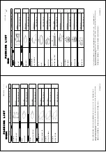
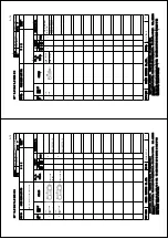
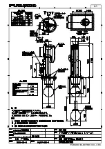
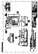
Page 55: ...D 1 13 Sep 2011 Y NISHIYAMA ...

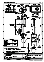
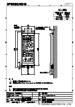
Page 56: ...D 2 13 Sep 2011 Y NISHIYAMA ...

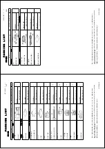
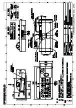
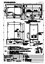
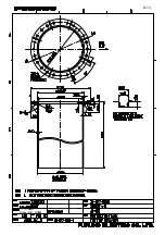
Page 57: ...D 3 5 Nov 2010 Y NISHIYAMA ...

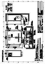
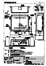
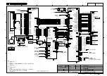
Page 58: ...D 4 Y Hatai ...

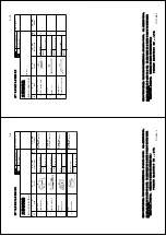
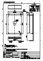
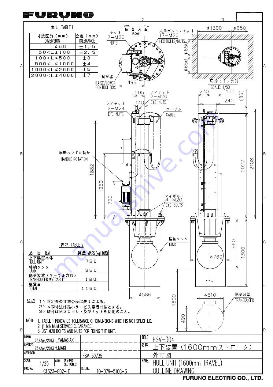
Page 59: ...23 Apr 2013 Y NISHIYAMA D 5 ...

Page 60: ...23 Apr 2013 Y NISHIYAMA D 6 ...

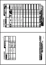
Page 61: ...D 7 13 Sep 2011 Y NISHIYAMA ...

Page 62: ...D 8 13 Sep 2011 Y NISHIYAMA ...

Page 63: ...13 Sep 2011 Y NISHIYAMA D 9 ...

Page 64: ...13 Sep 2011 Y NISHIYAMA D 10 ...

Page 65: ...13 Sep 2011 Y NISHIYAMA D 11 ...

Page 66: ...D 12 13 Sep 2011 Y NISHIYAMA ...

Page 67: ...11 Nov 2013 H MAKI Takahashi T Y Hatai D 13 ...

Page 68: ...6m 1 IV 2sq P P P P シロ ダイ ダイ シロ ミドリ ミドリ アオ シロ アオ シロ チャ チャ WHT ORG ORG WHT GRN BLU WHT BLU GRN WHT BRN BRN 1 2 3 4 5 FI 5002 JUNCTION BOX ジャンクションボックス 48VDC 15VDC FOR CANbus DVI2 SXGA UXGA WUXGA 2 4 4 DPYC 6 1 12 24VDC IV 8sq 1 1 2 1φ 50 60Hz DPYC 2 5 1 RU 1746B 2 RECTIFIER 整流器 2 100 115 220 230VAC 5 6 RJ45 RJ45 CN3 CN5 CN3 CN5 RJ45 RJ45 RJ45 RJ45 TT PP NN JJ CC BB AA Z Y W X V U T S R P N K J H F...

Reviews: