APPENDIX 2 ERROR CODE LIST
AP-9
133
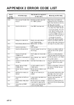
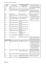
Resolver Signal Mal-
function
Error occurred in resolver
signal.
There is a problem in the po-
sition sensor inside the
transducer.
• Conduct the control box
test (see section 10.10.4)
and check that the RE-
SOLVER DRIVER STA-
TUS item is not shown as
“NG”.
• Reset the system power.
134
Resolver Signal DC
(COS side)
Resolver Signal side COS
disconnect.
There is a problem in the po-
sition sensor inside the trans-
ducer.
• Conduct the control box
test (see section 10.10.4)
and check that the RE-
SOLVER DRIVER STA-
TUS item is not shown as
“NG”.
• Reset the system power.
135
Resolver Signal DC
(SIN side)
Resolver Signal side SIN
disconnect.
136
Resolver R/D Converter
Fault
Resolver R/D Converter is
fault.
137
Resolver Internal TEMP
Fault
Resolver internal tempera-
ture is fault.
138
Motor Step-out
Motor Step-out occurred.
A step-out was detected in
the hull unit motor.
• Conduct the control box
test (see section 10.10.4)
and check that the MO-
TOR SELF TEST item is
not shown as “NG”.
• Reset the system power.
139
Motor Sensor Calibra-
tion Data Error
Motor Sensor Calibration
Data Error
There is a problem in the mo-
tion sensor. Reset the sys-
tem power.
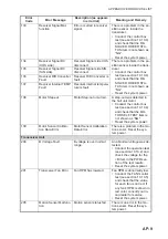
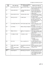
Transceiver Unit
200
B Voltage Fault
B voltage is over normal
range.
An abnormal voltage was de-
tected.
• Conduct the operation test
(see section 10.10.2) and
check the voltage for the
+B item in the PWR sec-
tion of the test results.
• Reset the system power.
201
Transceiver Fan Error
Fan RPM has lowered.
Fan RPM is abnormally low.
• Conduct the FAN monitor
test (see section 10.10.5)
and check that the value
for each fan is not red. If
any fan’s RPM is shown in
red color, consult your lo-
cal dealer for service.
• Reset the system power.
205
Motion Sensor Malfunc-
tion
Motion sensor status fail.
There is an error in the mo-
tion sensor. Reset the sys-
tem power.
Error
Code
Error Message
Description (as appears
in error list)
Meaning and Remedy
Summary of Contents for FSV-75
Page 1: ...OPERATOR S MANUAL www furuno com HALF CIRCLE COLOR SCANNING SONAR Model FSV 75 FSV 75 3D ...
Page 78: ...2 SLANT MODE 2 44 This page is intentionally left blank ...
Page 110: ...4 FISH FINDER MODE 4 12 This page is intentionally left blank ...
Page 144: ...5 3D MODE 5 34 This page is intentionally left blank ...
Page 148: ...6 NUMERIC GRAPHIC DATA DISPLAY 6 4 This page is intentionally left blank ...
Page 158: ...7 HOW TO CUSTOMIZE THE SONAR 7 10 This page is intentionally left blank ...
Page 216: ...10 MAINTENANCE 10 28 This page is intentionally left blank ...
Page 234: ...INDEX IN 3 W Warning messages 10 5 X XSECT ON OFF button 5 6 Z Zoom in out 5 4 ...
Page 235: ......

