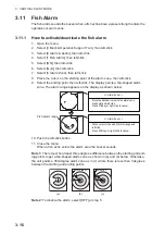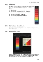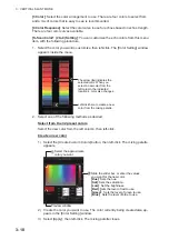
3. VERTICAL SLANT MODE
3-3
Note 2:
You can change the color of Event Marks, Fish Marks and Estimate Marks
from [1 Mark Color] (located at [0 Mark & Operation Support]
→
[2 Mark Color & Size]).
3.3
Display Range
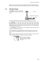
The
RANGE
knob selects the detection
range and nine ranges are preset at the
factory.
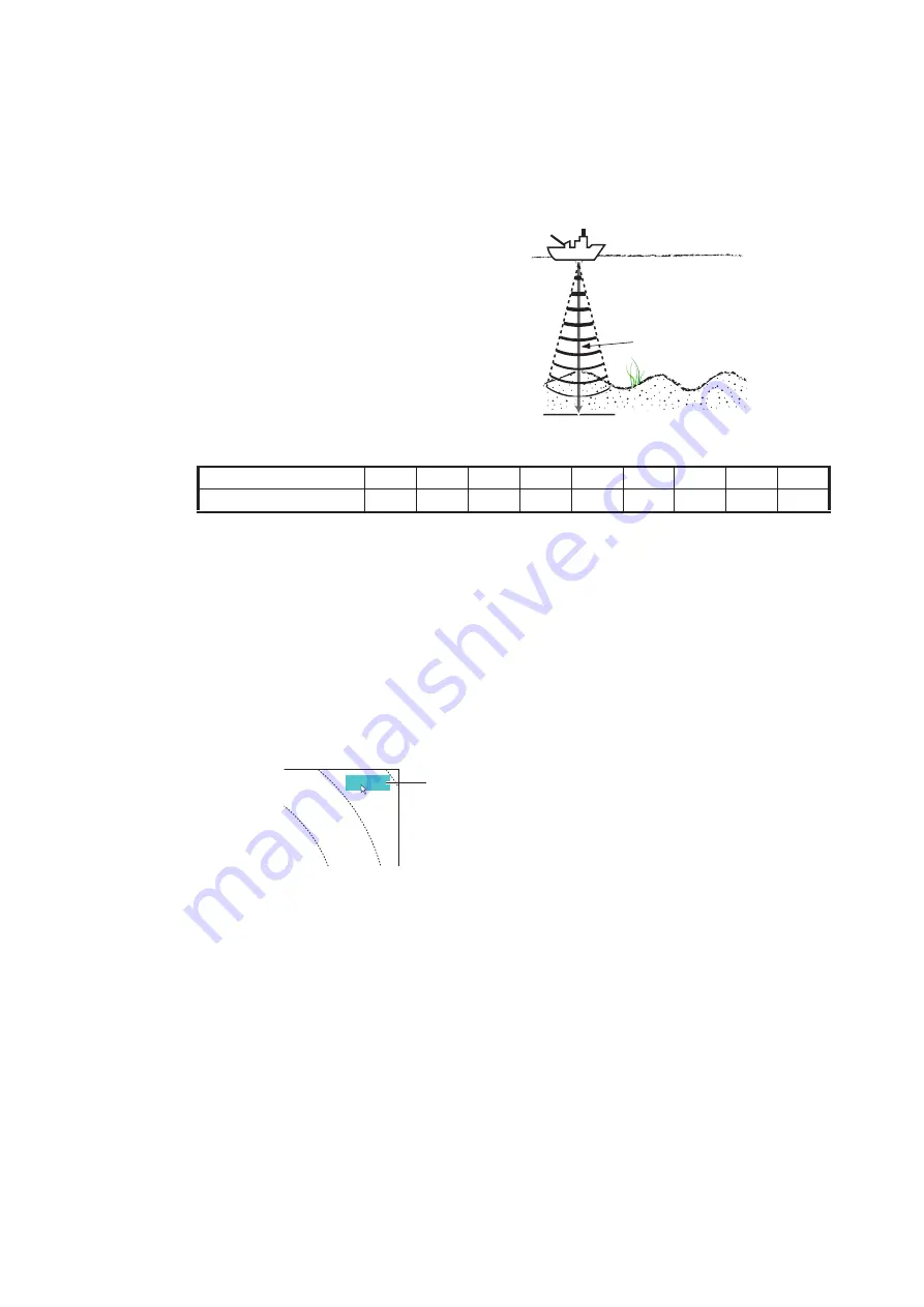
The following table shows the default settings for the display range (unit: m).
Note:
Ranges can be preset at [5 Scan Range] (located at [5 Record/Recall/Register]
→
[7 Register]). See section 9.1.2.
Turn the
RANGE
knob to select a range. Turn clockwise to increase the range, count-
er-clockwise to decrease the range.
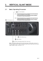
The range selected is momentarily displayed in large characters at the top of the
screen. Range is always displayed next to “R” at the top right-hand corner of the
screen.
Note:
The range can also be adjusted from the range indication. Put the cursor on the
range indication to highlight it in yellow then spin the scrollwheel.
Range No.
1
2
3
4
5
6
7
8
9
Detection range (m)
100
150
200
250
300
350
400
500
600
Surface
Bottom
Range displayed on display
Place the cursor on the range
setting, which is then highlighted.
Spin the scrollwheel to change
the setting.
400m
V R
0°
0°
TT
(
90° )
(
90° )
0°
0°
5.0
5.0
33
R0
R0
G
G
P
P
AUTO
AUTO
Summary of Contents for FSV-75
Page 1: ...OPERATOR S MANUAL www furuno com HALF CIRCLE COLOR SCANNING SONAR Model FSV 75 FSV 75 3D ...
Page 78: ...2 SLANT MODE 2 44 This page is intentionally left blank ...
Page 110: ...4 FISH FINDER MODE 4 12 This page is intentionally left blank ...
Page 144: ...5 3D MODE 5 34 This page is intentionally left blank ...
Page 148: ...6 NUMERIC GRAPHIC DATA DISPLAY 6 4 This page is intentionally left blank ...
Page 158: ...7 HOW TO CUSTOMIZE THE SONAR 7 10 This page is intentionally left blank ...
Page 216: ...10 MAINTENANCE 10 28 This page is intentionally left blank ...
Page 234: ...INDEX IN 3 W Warning messages 10 5 X XSECT ON OFF button 5 6 Z Zoom in out 5 4 ...
Page 235: ......


