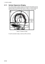
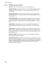
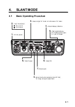
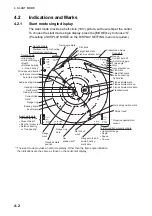
background image

4. SLANT MODE 

 4-2


4.2 

Indications and Marks 

4.2.1 

Slant mode single display 

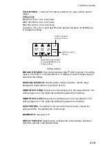
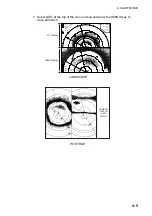
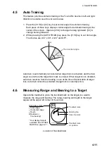
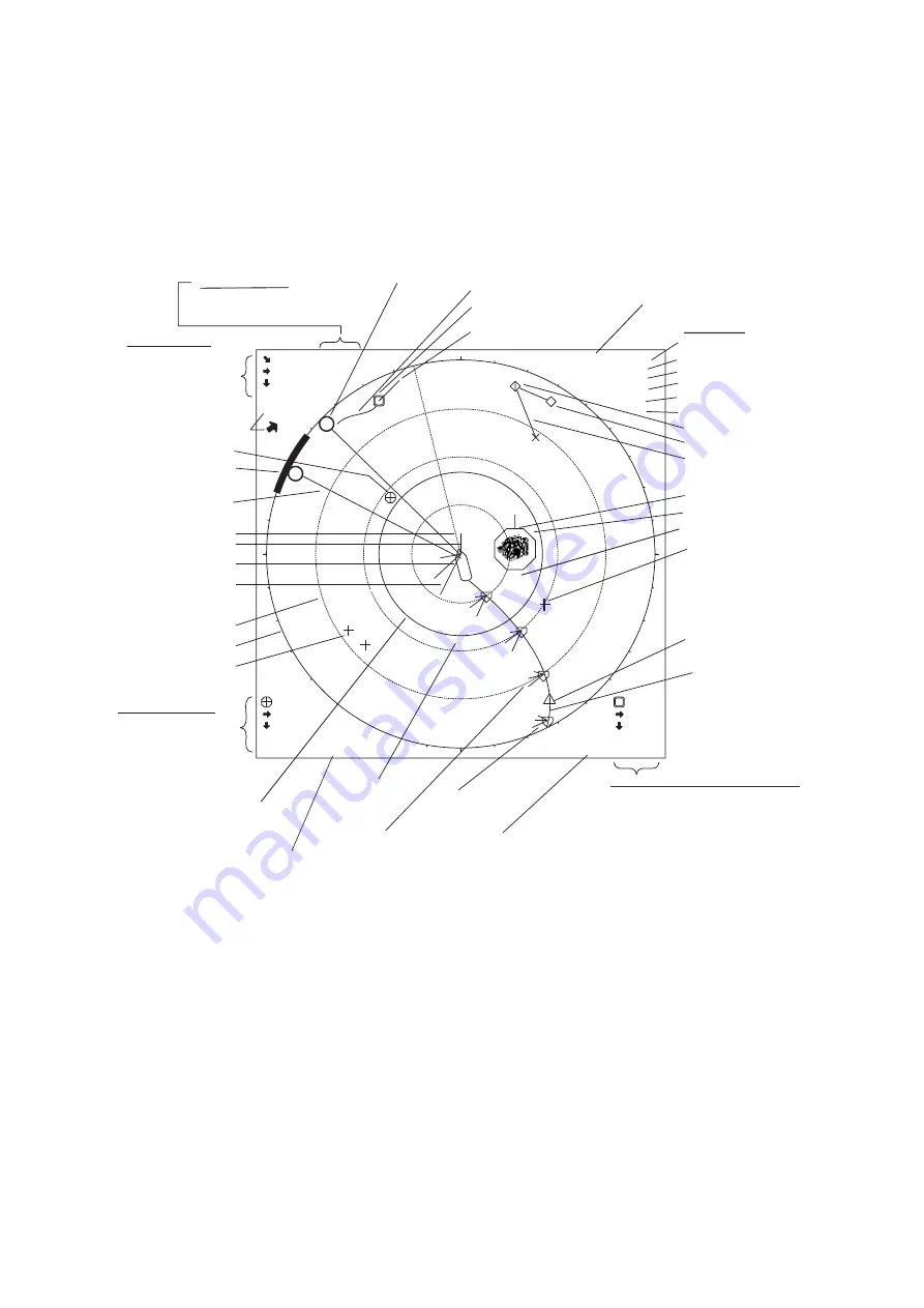
The slant mode provides a half-circle (180°) picture, with own ship at the center. 
To choose the slant mode single display, press the [MODE] key to choose “S”. 
(Presetting of DISPLAY MODE on the DISPLAY SETTING menu is required.) 
 

142m
45m

B

  115

°

R 400m

17

°

T

(21

°

)

G 10

         N-UP S

B

330

°

  (210m)

 48m

158m

148m

N

W

S

E

C

262

°

S 12.3kt

230m
70m

0.51NM
5:32

Trackball data

 Slant range

 Horizontal range

 Depth

 Relative bearing

   or True bearing*

Net shoot data
Distance run from shooting
Time from shooting

Event mark data

 Horizontal range

 Present depth

 Depth at measured

 Relative bearing

   or True bearing*

Latest event mark

Trackball mark

Target lock mark

Event mark

Bearing scale

Range ring

Own ship mark

Heading mark

Range ring
data

Net 
sonde mark*

Net shoot
mark

Ship's track*

Target lock/fish movement data

 Horizontal range

 Depth

 Speed

 Course

Latest fish mark

Fish mark

Fish estimate mark
Fish estimate mark no.
Fish estimate mark data

3

2

1

North mark*

Current (tide)
mark*

3

2

1

3

2

1

3

2

1

1

2

  P8

B

290

°

R 146m

Range mark and
audio bearing
mark data

Scan data
Range
Current auto tilt
(Auto train angle
Train angle**
Gain
User program no.

3

2

1

1

2

3

Own ship position mark

Fish track

Fish movement vector

Auto train mark

Line connecting
fish marks

W

12m/s

Wind speed, direction*

Audio bearing mark

Requires appropriate

  sensor.

85

1

150

A

Range
mark

Presentation mode

  34

°

56.789N

123

°

45.678E

Trackball mark
position

BO 50

°

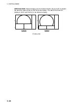
** The slant mode provides a half-circle display. Other than the train angle indication,
    the indications are the same as those on the horizontal display.

S

Train angle mark


Summary of Contents for FSV-84

Page 1: ...COLOR SCANNING SONAR FSV 84 ...

Page 2: ...inomiya 662 8580 JAPAN Telephone Telephone 0798 65 2111 0798 65 2111 Fax Fax 0798 65 4200 0798 65 4200 FIRST EDITION FIRST EDITION SEP SEP 2006 2006 Printed in Japan Printed in Japan All rights reserved All rights reserved B B FEB FEB 20 2007 20 2007 Pub No Pub No OME 13290 OME 13290 00015742711 00015742711 DAMI DAMI FSV 84 FSV 84 00015742711 00015742711 0 0 0 1 5 7 4 2 7 1 1 0 0 0 1 5 7 4 2 7 1 1...

Page 3: ...s manual may not match the screens you see on your display The screen you see depends on your system configuration and equipment settings Store this manual in a convenient place for future reference FURUNO will assume no responsibility for the damage caused by improper use or modification of the equipment including software by an unauthorized agent or a third party When it is time to discard this ...

Page 4: ...pment can cause fire or electrical shock Contact a FURUNO agent for service WARNING Do not disassemble or modify the equipment Fire electrical shock or serious injury can result Do not install the equipment where it may be subject to rain or water splash Fire or electrical shock can result if water leaks in the equipment Use the proper fuse Use of a wrong fuse can result in damage to the equipment...

Page 5: ...of the system Do not remove the labels If a label is missing or damaged contact a FURUNO agent or dealer about replacement WARNING To avoid electrical shock do not remove cover No user serviceable parts inside Name Warning Label 1 Type 86 003 1011 1 Code No 100 236 231 DANGER Keep fingers away from gears Shaft may cause injury Keep away froom moving shaft Name Warning Label Type 10 071 5313 Code N...

Page 6: ...SAFETY INSTRUCTIONS iv This page intentionally left blank ...

Page 7: ...ations and Marks 2 2 2 2 1 Horizontal mode 2 2 2 2 2 Horizontal2 mode 2 3 2 3 Display Range 2 7 2 4 Tilt Angle 2 8 2 4 1 Setting the tilt angle 2 8 2 4 2 Automatic tilt 2 9 2 4 3 Relation between bottom echo and tilt angle 2 11 2 4 4 Tilt angle for surface fish 2 12 2 4 5 Suitable tilt angle 2 13 2 5 Measuring Range and Bearing to a Target 2 14 2 6 Eliminating Weak Echoes 2 15 2 7 Suppressing Bott...

Page 8: ... mode 2 34 2 14 Fish Alarm 2 35 2 15 Relocating Fish School for Easy Observation 2 37 2 16 Comparing Fish School Concentration 2 38 2 17 Measuring Fish School Speed 2 39 2 17 1 Entering fish marks 2 39 2 17 2 Deleting fish marks 2 40 2 18 Event Mark Own Ship Position Mark 2 41 2 18 1 Entering an event mark 2 41 2 18 2 Entering an own ship position mark 2 42 2 18 3 Deleting an event mark own ship p...

Page 9: ...ifying noise source 3 12 3 9 2 Interference rejector 3 12 3 9 3 Noise limiter 3 13 3 9 4 Shifting Tx frequency 3 13 3 9 5 Echo average 3 13 3 9 6 Reverberation reduction 3 13 3 9 7 Suppressing gain of bottom echo 3 14 3 9 8 Suppressing sidelobes 3 14 3 10 Adjusting Beamwidth 3 15 3 11 Vertical Expansion Display 3 16 3 12 OTHERS Menu 3 17 3 12 1 Displaying the OTHERS menu 3 17 3 12 2 OTHERS menu de...

Page 10: ...2 1 Selecting target lock type 4 22 4 12 2 Fish school tracking mode 4 23 4 12 3 Position tracking mode 4 24 4 12 4 TARGET LOCK menu 4 25 4 13 Detecting Fish Schools Aurally 4 26 4 13 1 Selecting direction 4 26 4 13 2 Selecting audio sector 4 27 4 13 3 Reverberation 4 27 4 14 Offcenter 4 28 4 14 1 Manual offcenter 4 28 4 14 2 Automatic offcenter 4 29 4 15 Fish Alarm 4 30 4 16 Comparing Fish School...

Page 11: ... Procedure 6 1 6 2 Sample History Display 6 2 6 3 How to Interpret Set the History Display 6 3 6 3 1 Interpreting the history display 6 3 6 3 2 Setting the history marker 6 4 6 3 3 Setting the width of the history marker 6 5 6 3 4 Setting the picture advance mode 6 6 7 NUMERIC GRAPHIC DATA DISPLAY 7 1 7 1 Full Numeric Graphic Data Display 7 1 7 2 Abbreviated Numeric Graphic Data Display 7 2 7 3 Nu...

Page 12: ...ading Deleting Files 10 3 10 3 Formatting Memory Cards 10 4 11 MAINTENANCE TROUBLESHOOTING 11 1 11 1 Preventive Maintenance 11 1 11 2 Hull Unit Maintenance 11 2 11 3 Fuse Replacement 11 3 11 4 Troubleshooting 11 4 11 5 Warning Messages 11 5 11 6 Error Codes 11 6 11 7 Status Messages 11 7 11 8 Tests 11 7 11 8 1 TEST menu 11 7 11 8 2 Board test 11 8 11 8 3 Panel test 11 10 11 8 4 Test pattern 11 11 ...

Page 13: ...d purchasing FURUNO equipment Features The FSV 84 is a full circle multibeam electronic color scanning sonar which detects and displays fish schools on a 21 inch non glare high resolution color monitor System also available without monitor The main features of the FSV 84 are Cylindrical sphere transducer provides 90 degrees vertical detection Vivid 32 color echo strength dependent display for impr...

Page 14: ...echoes along user selected area through built in loudspeaker Fish mark estimates fish speed Fish estimate feature compares volume of two fish schools Target lock automatically tracks fish school Net course mark shows probable drift of net against tide ...

Page 15: ...0 Current Indicator E S Interface VI 1100A Net Recorder VI 1100A Net Sonde Junction Box CS 170 VI 1100A Net Sonde External Interface CS 120A Note 1 100 115 220 230 VAC 1φ 50 60 Hz External Monitor PROCESOR UNIT FSV 8402 CONTROL UNIT FSV 8401 External equipment Option 100 110 115 220 230 VAC 1φ 50 60 Hz HULL UNIT FSV 8432 FSV 8442 Speed Log Speed Log CONTROL UNIT FSV 8401 TRANSCEIVER UNIT FSV 841A ...

Page 16: ...C 3φ 50 60 Hz HULL UNIT FSV 8432 FSV 8442 Note 1 Power Kit option installed in processor unit required to connect CS 120A TRANSCEIVER UNIT FSV 841A 100 110 115 220 230 VAC 1φ 50 60 Hz Loudspeaker Sub Monitor Echo Sounder Current Indicator other Navigator 1 Navigator 2 AD Converter AD 100 Speed Log CONTROL UNIT FSV 8401 MONITOR UNIT FSV 2400 Speed Log CONTROL UNIT FSV 8401 Net Sonde External equipm...

Page 17: ...rizontal mode vertical bearing mark vertical mode Off 12 24 36 Off In vertical combination mode switches between normal and expansion display Displays range and audio bearing marks to monitor echoes along audio bearing mark horizontal mode Trackball Positions trackball mark Selects items options on menu Opens closes menu Off centers the picture Deletes trackball selected mark SHOOT Displays net da...

Page 18: ...aised Note While raising the transducer the ship speed must be no more than 15 kts to prevent damage to the transducer and hull unit 2 Press the POWER OFF switch for more than one second after the key lights steadily Note The transducer is automatically retracted into the tank if the POWER OFF switch is pressed before retracting the transducer However for safety purposes make it a habit to retract...

Page 19: ... takes about 21 seconds for full protrusion in case of 800 mm stroke and 28 seconds in case of 1100 mm stroke In normal use fully lower the transducer If the transducer becomes entangled in the net for some reason partially raise the transducer with the key This raises the transducer by 400 mm 1 3 2 Raising the transducer Press the key to raise the transducer The lamp above the switch blinks while...

Page 20: ... SETTING V SCAN SETTING OTHERS TX PULSE LENGTH H 9 TX POWER H 9 TVG NEAR H 0 TVG MEDIUM H 0 TVG FAR H 0 AGC H 0 2ND AGC H 0 ECHO AVERAGE H 0 COLOR H COLOR 1 COLOR RESPONSE H COLOR CURVE 3 Main menu default 2 Use the trackball to select OTHERS and press the MENU key ES1 SETTING ES2 SETTING ERASE MARKS DISPLAY SETTING ALARM AUDIO PRESET MEMORY CARD INITIAL SETTING OTHERS MENU QUIT QUIT OTHERS menu ...

Page 21: ...10 KEY BEEP VOLUME 5 OTHERS MENU QUIT QUIT QUIT DISPLAY SETTING menu 4 Select DIMMER with the trackball and press the MENU key to open the dialog box QUIT CANCEL DIALOG BOX FOR SETTING NUMERIC DATA Select raise setting or lower setting with the trackball and press MENU key to change setting Select QUIT to finish CANCEL to cancel operation Dialog box for setting numeric value 5 Select S raise setti...

Page 22: ... Horizontal1 Horizontal2 Vertical1 Vertical 1 Vertical 2 and History You can program the MODE key to show any or all of the modes mentioned above For further details see DISPLAY MODE on page 9 2 Note that the MODE key may be programmed to show a pull down menu instead For further details see MODE SELECTION on page 9 2 In this case the procedure for mode selection is as follows 1 Press the MODE key...

Page 23: ... not shown For meaning of marks and indications see respective indications and marks description illustration in applicable chapter Horizontal mode This mode provides 360 degree coverage around the vessel and it is useful for general search For further details see Chapter 2 N W S E NUMERIC GRAPHIC DATA DISPLAY Horizontal mode display ...

Page 24: ...e DISPLAY SETTING menu For further details see Chapter 2 N S 3 2000 2 3 1 3 2 1 NUMERIC GRAPHIC DATA DISPLAY N 1 85 3 2 1 S 3 2 1 1 3 2 2 1 3 2000 2 3 1 3 2 1 N W E 2 1 1 N W E 2 1 1 85 1 NUMERIC GRAPHIC DATA DISPLAY PORTRAIT LANDSCAPE N W S E 3 300 2 3 1 3 2 1 N W S E 3 2 1 3 2 1 1 3 2 2 1 3 2000 2 3 1 3 2 1 1 85 1 2 NUMERIC GRAPHIC DATA DISPLAY N W S E 3 300 2 3 1 3 2 1 N W S E 3 2 1 3 2 1 1 3 2...

Page 25: ...2 3kt 975m 153m B 234 R 1056m B 128 164m 156m 1475m 32 52 150N 132 12 150E 1 R2000m AUTO 17 T 21 G 10 0 N UP P 8 P 6 S H 3 2 1 3 2 1 3 N S HEADING 321 SHIP COURSE 335 SHIP SPEED 12 5kt LAT LON DGPS 000 000 32 52 150N 132 12 150E DEPTH 321m WATER CURR C1 1 2kt 342 C2 0 8kt 298 C3 0 4kt 256 NET DEPTH S1 134m S2 178m S3 213m FISH HISTOGRAM 1 Scan1 10 3 C WATER TEMP 8 12 10 0 10 20m in 10 0 678m 346m ...

Page 26: ...DATA DISPLAY 1000 1500 500 1000 1500 500 1000 500 N W S E 2000 NUMERIC GRAPHIC DATA DISPLAY 1000 1500 500 1000 500 Vertical 1 Display Vertical 1 Display Vertical 2 Display V1 mode V1 V2 mode V 52 V1 and V2 displays V1 ES1 or ES2 mode The V1 ES1 or ES2 combines the vertical 1 display with the picture from an echo sounder or a net recorder N W S E 2000 NUMERIC GRAPHIC DATA DISPLAY 1000 500 1000 500 ...

Page 27: ... direction the latest echoes at the top and the oldest at the bottom This mode is useful for observing fish echoes over time For further details see Chapter 6 N W S E NUMERIC GRAPHIC DATA DISPLAY Horizontal Display History Display History display ES1 mode The ES1 mode shows the echo sounder display For further details see Chapter 5 N W S E NUMERIC GRAPHIC DATA DISPLAY Echo Sounder Display ES1 Hori...

Page 28: ...ures Note that this mode can also show the echo sounder picture N W S E NUMERIC GRAPHIC DATA DISPLAY Horizontal Display Net Recorder Display ES2 ES2 display shown downward picture ES1 ES2 mode The ES1 ES2 mode shows the echo sounder and net recorder displays N W S E Net Recorder Display ES2 Echo Sounder Display ES1 NUMERIC GRAPHIC DATA DISPLAY 30 60 0 10 20 0 Horizontal Display ES1 ES2 display ...

Page 29: ...l somewhere between positions 3 and 7 1 If the horizontal and vertical modes are active press the HSV key to show the range and gain indications of the mode you wish to adjust in yellow Pressing the HSV key changes the range and gain indication in yellow between horizontal1 and horizontal2 or horizontal and vertical alternately 2 Adjust the GAIN control New gain setting is momentarily displayed in...

Page 30: ...t QUIT with trackball and then press MENU key to close menu Select menu with trackball and then press MENU key to display Ellipsis mark indicates a menu MENU QUIT H SCAN SETTING V SCAN SETTING OTHERS TX PULSE LENGTH H 9 TX POWER H 9 TVG NEAR H 0 TVG MEDIUM H 0 TVG FAR H 0 AGC H 0 2ND AGC H 0 ECHO AVERAGE H 0 COLOR H COLOR 1 COLOR RESPONSE H COLOR CURVE 3 Main menu Note The menus illustrations in t...

Page 31: ... 0 REVERBERATION SIDE LOBE SUPPRESS 1 0 MENU QUIT INT REJECT 0 0 0 QUIT MENU TITLE Select QUIT with trackball and press the MENU key to close menu currently open Menu items and current settings Choose QUIT to close all menus Pointer shows current selection FREQ SHIFT 0 FREQ BEARING SET 180 OTHERS NEAR AGC 0 BOTTOM SUPPRESS 0 H SCAN SETTING menu Note In the S mode combination display the HSV key fu...

Page 32: ... REJECT 0 0 0 QUIT FREQ SHIFT 0 FREQ BEARING SET 180 OTHERS NEAR AGC 0 BOTTOM SUPPRESS 0 NOISE LIMITER 2 H SCAN SETTING menu 4 Select S raise setting or T lower setting with the trackball and press the MENU key to change setting Note For items having options the arrows in the dialog box are replaced with appropriate options For example the dialog box for selection of picture advance speed in the e...

Page 33: ... select an item the message below appears To change the setting of the selected item select YES and press the MENU key and the dialog box for the item selected appears To escape select NO and press the MENU key You may wish not to show the message below that is disable the setting protection feature For further details see ITEM ATTRIBUTION on page 9 16 CAUTION THIS ITEM IS DEFINED AS NON CHANGEABL...

Page 34: ...1 OPERATIONAL OVERVIEW 1 18 This page intentionally left blank ...

Page 35: ...horizontal display 6 Select range 3 Adjust display brilliance 5 Press to choose the screen horizontal or vertical or horizontal1 or horizontal2 to adjust gain and range 7 Adjust gain 8 Set tilt angle FSV 84 HSV V1 S 2 Lower transducer Mid protrusion Full protrusion Control unit ...

Page 36: ...k Target lock mark Event mark Bearing scale Range ring Own ship mark Heading mark Range ring data Net sonde mark Net shoot mark Ship s track Target lock fish movement data Horizontal range Depth Speed Course Latest fish mark Fish mark Fish estimate mark Fish estimate mark no Fish estimate mark data 3 2 1 North mark Current tide mark 3 2 1 3 2 1 3 2 1 1 2 P 8 B 290 R 146m Range mark and audio beari...

Page 37: ...open the main menu MENU QUIT H SCAN SETTING V SCAN SETTING OTHERS TX PULSELENGTH H 9 TX POWER H 9 TVG NEAR H 0 TVG MEDIUM H 0 TVG FAR H 0 AGC H 0 2ND AGC H 0 ECHO AVERAGE H 0 COLOR H COLOR 1 COLOR RESPONSE H COLOR CURVE 3 Main Menu 2 Select OTHERS with the trackball and press the MENU key to open the OTHERS menu ES1 SETTING ES2 SETTING ERASE MARKS DISPLAY SETTING ALARM AUDIO PRESET MEMORY CARD INI...

Page 38: ...LT LEVER TILT S AUTO OFF CENTER OFF H SLICE WIDTH 16 H SLICE PICT ADVC KP SYNC NET COURSE MARK ENTER MANUAL DEGAUSS EXECUTE AUTO DEGAUSS INTSENSOR DIMMER 10 KEY BEEP VOLUME 5 OTHERS MENU QUIT QUIT QUIT DISPLAY SETTING menu 4 Select H2 S DISPLAY and press the MENU key QUIT CANCEL LANDSCAPE PORTRAIT RIGHT INSET LEFT INSET Dialog box for setting combination 5 Select the desired combination with the t...

Page 39: ...156m 2975m 3902m 85 C 256 S 12 3kt 2975m 153m 5 32 9 83NM 2 1 1 P 8 B 234 R 1056m W 12m s N N R 1000m 24 T G 7 5 P 6 2 1 1 1 32 52 150N 132 12 150E H1 H2 The range tilt gain and user program are set independently for each display H1 display H2 display LANDSCAPE N S 3 2000 2 3 1 3 2 1 NUMERIC GRAPHIC DATA DISPLAY N 1 85 3 2 1 S 3 2 1 1 3 2 2 1 3 2000 2 3 1 3 2 1 PORTRAIT ...

Page 40: ...0 2 3 1 3 2 1 N W S E 3 2 1 3 2 1 1 3 2 2 1 3 2000 2 3 1 3 2 1 1 85 1 2 NUMERIC GRAPHIC DATA DISPLAY LEFT INSET N W S E 3 300 2 3 1 3 2 1 N W S E 3 2 1 3 2 1 1 3 2 2 1 3 2000 2 3 1 3 2 1 1 85 1 2 NUMERIC GRAPHIC DATA DISPLAY RIGHT INSET ...

Page 41: ...e default ranges in meters Range Setting 1 2 3 4 5 6 Range 100 200 400 600 800 1000 1 If the two horizontal displays slant display or the horizontal and vertical displays are active press the HSV key to show the range and gain indications of the horizontal mode in yellow This step is not necessary when only the horizontal mode is active Range and gain indications are shown in white on other modes ...

Page 42: ...ng the tilt angle To manually set a tilt angle operate the TILT control Watch the tilt angle indication and tilt angle indicator at the top right corner of the screen Select tilt angle depending on target fish For surface fish select a shallow angle about 5 and for bottom fish a deep angle Transducer 5 degree 90 degree Tilt angle setting range 0 degree horizontal direction tilt angle 0 degree Note...

Page 43: ...eriod One trans Tilt angle changes in 2 increments for asterisk marked width 1 increments for all other widths Automatic tilt range wide with AUTO TILT key Range Width 1 Width 2 Width 3 Period 60 100 150 200 300 400 500 600 700 800 900 1000 1100 and more 10 As above As above 8 6 4 2 16 As above As above As above 12 8 4 20 As above As above As above 16 12 6 Period One trans Period Four trans Period...

Page 44: ...are set to 800 m 8 and width 1 respectively the tilt angle changes at each transmission as follows 8 9 8 7 8 Tilt angle setting Auto tilt concept Note The AUTO TILT key is inoperative when the target lock function is active or is made active Auto tilt is resumed once target lock is disabled ...

Page 45: ... Case 3 Tilt angle 0 to 5 This tilt angle may or may not capture the bottom since the returning echo is weak Fish school is located close to the bottom Case 1 Case 2 Case 3 Case 1 Fish school a Bottom Fish school a Fish school a Case 2 Case 3 Bottom Bottom Fish school b Fish echo and tilt angle Points to consider Normally a vertically distributed fish school is a better sonar target than the botto...

Page 46: ...ucer and displayed on the screen as sea surface reflections When the sea is calm since the sound is reflected just like a light hitting a mirror at a low incident angle it propagates away and the sea surface reflections become negligible However if the sea is not calm enough they will become dominant and interfere with observation of wanted echoes To minimize these sea surface reflections and to s...

Page 47: ...the suitable tilt angle for a given depth detection range Range m Vertical width of sonar beam 18 31 m 100 m 100 m 300 m 93 m 200 m Depth m 62 m Tilt angle and beam coverage vertical beamwidth 18 at 6dB 100 200 200 400 300 600 400 800 Tilt 0 0 9 20 40 40 80 60 120 80 160 100 200 200 400 Tilt 5 0 14 Tilt 15 6 24 Grey Tilt 10 1 19 6dB Tilt angle and beam coverage ...

Page 48: ...ppear at the upper left corner of the screen Trackball position may also be show in latitude and longitude For further details see CURSOR POSITION on page 9 11 Trackball mark TRACKBALL DATA Slant range Horizontal range Depth B Relative or True bearing Four display formats available See OTHER MARKS on page 9 11 B Heading line Own ship mark 34 56 789N 123 45 678E Trackball mark L L position Location...

Page 49: ...loss of sound in water amplification of echoes on short range is suppressed and gradually increased as range increases so that similar targets are displayed in the similar intensities irrespective of the ranges to them The FSV 84 has three TVG functions NEAR MEDIUM and FAR and they mainly compensate for propagation loss on short middle and long ranges respectively centered at the ranges shown belo...

Page 50: ...PPRESS 0 SIDELOBE SUPPRESS 1 H SCAN SETTING menu 3 Select TVG NEAR with the trackball and press the MENU key to show the dialog box QUIT CANCEL Numeric data entry dialog box 4 Use the trackball to select S or T and press the MENU key to set The setting range is 5 to 5 The higher the setting the greater the TVG effect 5 Select QUIT and press the MENU key 6 Repeat steps 3 5 to set TVG MEDIUM and TVG...

Page 51: ...he OTHERS sub menu in the H SCAN SETTING menu Also adjust the setting of NEAR AGC referring to next section 2 7 Suppressing Bottom Tail 2 7 1 Adjust AGC The AGC functions to automatically reduce the receiver gain only against strong echoes such as the bottom or a large fish school Since weak echoes remain unaffected a small fish school becomes easier to detect Adjust it so that the AGC works only ...

Page 52: ...the setting the longer the pulse length 5 Select QUIT and press the MENU key 6 Select QUIT at the top of the menu screen and press the MENU key to close all menus 2 7 3 Adjust 2nd AGC While it is ideal to suppress bottom echoes with the AGC alone there are some fishing grounds where this is not possible The high power sonar has the advantage of long range detection but this can also be a disadvant...

Page 53: ...mally set it between 3 and 4 however this setting depends on the sea area Do not set it too high all echoes including noise from near distance may be painted in red 1 Press the MENU key to open the menu 2 Select H SCAN SETTING menu and press the MENU key 3 Select NEAR AGC and press the MENU key 4 Adjust setting from the dialog box as appropriate and press the MENU key The setting range is 0 10 The...

Page 54: ...clearer when output power is reduced rather than when the GAIN is decreased as illustrated below Fish echo Fish echo weakened Fish echo INCORRECT METHOD CORRECT METHOD Reduce TX POWER with GAIN kept constant TVG and AGC adjusted with TX POWER kept high How to suppress bottom and sea surface reflections in shallow waters 1 Press the MENU key to open the menu 2 Select the H SCAN SETTING menu and pre...

Page 55: ... the boat at various speeds to check if the noise is speed dependent If neither of the above two steps has effect on the picture adjust one of the following 2 9 2 Interference rejector This control is similar to the interference rejector on echo sounders and radars It is effective for rejecting random noise and sea surface reflections in rough sea conditions Set it so that noise is just eliminated...

Page 56: ...UIT and press the MENU key 6 Select QUIT at the top of the menu screen and press the MENU key to close all menus Note When the sonar is used in shallow water with the range set between 60 m and 200 m and Tx cycle at 9 bottom reflections caused by the 2nd to the last transmission may appear on near ranges Lower the Tx interval by 2 or 3 steps to suppress them 2 9 4 Shifting Tx frequency If interfer...

Page 57: ...onger echoes remain on the screen 2 9 7 Reverberation reduction You may choose the length of reverberation for the echo signal in the H SCAN SETTING menu The larger the value the shorter the reverberation which makes it easer to see the echo signal The setting range is 0 3 2 9 8 Setting reference bearing for frequency change The FREQ BEARING SET function in the H SCAN SETTING menu is provided for ...

Page 58: ...atively shallow and the bottom is rocky and hard strong signals are detected by the sidelobe To reduce the effect of sidelobes adjust SIDELOBE SUPPRESS from the H SCAN SETTING menu The setting range is 3 to 3 and the default setting is 0 The higher the setting the greater the sidelobe suppression If there is a difference between the port and starboard side images use a minus setting ...

Page 59: ... NORMAL ABSORPTION COEFF 23 5dB OTHERS menu 4 Select BEAMWIDTH and press the MENU key to open the dialog box MENU QUIT QUIT OTHERS H SCAN SETTING QUIT QUIT BEAMWIDTH BEAMWIDTH A 0 BEAMWIDTH B 0 5 Select BEAMWIDTH A and set appropriate value The higher the setting the sharper the horizontal resolution The setting range is 4 to 5 plus AR and the default setting is 0 AR means AUTO RANGE and it automa...

Page 60: ... key 4 Select YES and press the MENU key to confirm the CAUTION indicated 5 Select TARGET LOCK and press the MENU key INITIAL SETTING MENU QUIT QUIT QUIT TARGET LOCK OTHERS TRACKING METHOD FISH TILT INTERLOCK TILT RANGE MARK INTERLOCK ESTIMATE MARK TRACKING DATA H V THRESHOLD 16 BOTTOM THRESHOLD 3 TARGET SPEED LIMIT 5kt SMOOTHING 0 5 TARGET SPD UPDATE 60SEC TARGET LOCK WINDOW NORMAL DIMENSION SETU...

Page 61: ... appears on the fish school with a vector extending from its edge This vector shows estimated target position after elapsed of preset vector time The target lock mark is also inscribed on the vertical display however no vector appears If the target is lost the target lock mark changes to red color and the tracking mode changes to position mode see next section at that position When the FSV 84 dete...

Page 62: ... 3 Press the TARGET LOCK key to inscribe the target lock mark at the location selected The target lock mark is also inscribed on the vertical display Tilt range and vertical bearing are automatically adjusted to track the location Using the figure above as an example the target lock mark is placed on location E Then the equipment remembers the location of E and automatically changes the tilt angle...

Page 63: ... use horizontal or both horizontal and vertical THRESHOLD Selects the weakest echo color number to track The setting range is 1 to 30 BOTTOM THRESHOLD When a target is judged as a bottom echo raise this setting to differentiate bottom from target The setting range is 0 to 5 The setting range is 0 to 5 TARGET SPEED LIMIT Sets maximum fish speed to track The setting range is 1kt to 15kt SMOOTHING Se...

Page 64: ...en the school is going away 2 12 1 Selecting direction In the default setting the audio function is on and the audio sector is 30 1 Operate the trackball to place the trackball mark on the direction you want to monitor through the speaker 2 Press the R B AUDIO key The audio bearing mark appears on the bearing selected in a 30 60 90 180 or 330 sector centering the audio bearing mark Echoes are moni...

Page 65: ...ARM LEVEL 16 ALARM ZONE SHIP SPEED ALARM ON AUDIO ON AUDIO SECTOR 30 REVERBERATION 0 QUIT ALARM AUDIO menu 4 Select AUDIO SECTOR and press the MENU key to open the dialog box CANCEL 30 60 90 180 330 QUIT Audio sector dialog box 5 Select desired audio sector among 30 60 90 180 330 and press the MENU key 6 Select QUIT and press the MENU key 7 Select QUIT at the top of the menu screen and press the M...

Page 66: ... 24 36 and OFF Watch the auto train mark to know the currently selected sector The chosen sector appears in large characters for five seconds at the top of the screen To turn off automatic training select OFF at step 2 Audio bearing mark Auto train mark Auto train sector A Indications related to automatic training 2 12 4 Reverberation You may choose the length of reverberation for the audio signal...

Page 67: ...ment Echoes from fish and the bottom move on the screen relative to own ship s movement Course up The display is oriented according to course Own ship position is fixed at the screen center Echoes from fish and the bottom move on the screen relative to own ship s movement Targets are displayed at ship s bow True Motion Stationary objects are fixed and own ship and fish echoes move on the display i...

Page 68: ...E PICT ADVC KP SYNC NET COURSE MARK ENTER MANUAL DEGAUSS EXECUTE AUTO DEGAUSS INTSENSOR DIMMER 10 KEY BEEP VOLUME 5 OTHERS MENU QUIT QUIT QUIT DISPLAY SETUP menu 4 Select PRESENTATION MODE and press the MENU key to open the dialog box CANCEL HEAD UP NORTH UP COURSE UP TRUE MOTION QUIT Presentation mode dialog box 5 Select presentation mode desired and press the MENU key 6 Select QUIT and press the...

Page 69: ... 0 QUIT ALARM AUDIO menu 4 Select FISH ALARM and press the MENU key to open the dialog box CANCEL OFF ON QUIT Fish alarm status dialog box 5 Select ON select QUIT and then press the MENU key To cancel the fish alarm select OFF instead of ON 6 Select ALARM ZONE and press the MENU key 7 Operate the trackball to place the trackball mark on the starting point of the alarm zone 8 Press the MENU key 9 R...

Page 70: ...larm zone as shown in a and b below Otherwise the unit paints a 360 degree alarm zone as in c where there is less than 3 degrees between the starting and ending points and d where the bearing marker has been rotated one full turn More than 3 Within 3 a b c d How to create desired alarm zone Note 2 The echo strength which triggers the alarm can be set with ALARM LEVEL on the ALARM AUDIO menu The se...

Page 71: ...e the trackball mark on the position where you want to relocate the own ship mark 2 Press the OFF CENTER key 3 To move the own ship mark back to the screen center press the OFF CENTER key again Own ship mark Set trackball mark here for example Press OFF CENTER key Fish school Own ship mark moves to trackball mark position Fish school How to use offcenter ...

Page 72: ...nd 100 below the estimate mark When the area inside the mark is filled in reddish brown volume figure is said to be 100 3 Operate the trackball to place the trackball mark on another fish school and press the ESTIMATE 2 key 4 Compare estimate figures for each fish school by observing estimate mark data and the fish histogram 5 To turn off the estimate marks press their respective keys N W S E SCAN...

Page 73: ... any earlier fish marks are shown with an X The distance between the two fish marks and fish school course and speed appear at the bottom right hand corner of the horizontal display area Latest fish mark Latest fish mark 2nd latest fish mark WAIT 1 2 MINUTES X Earlier fish mark max 8 Place trackball mark on a fish school and press FISH key Place trackball mark on fish school s current location and...

Page 74: ...l to place the trackball mark on the fish mark you want to erase The color of the fish mark changes from white to red when the fish mark is correctly selected Press the DELETE MARK key to delete the fish mark Deleting fish marks through the menu 1 Press the MENU key to show the menu 2 Select OTHERS and press the MENU key 3 Select ERASE MARKS and press the MENU key ERASE MARKS MENU QUIT QUIT OTHERS...

Page 75: ...ke room for the latest The own ship position mark red is used to mark current position 2 18 1 Entering an event mark 1 Set the trackball mark where you want to place an event mark 2 Press the EVENT key The horizontal range depth and bearing to the event mark appear at the bottom left corner of the horizontal display area 234 Horizontal range m from own ship mark 19 Present depth m to mark 35 Depth...

Page 76: ...ship position mark Place the trackball mark close to the center of the own ship mark and press the EVENT key Ten own ship position marks may be inscribed When the capacity for own ship position marks is reached the earliest own ship position mark is automatically erased 2 18 3 Deleting an event mark own ship position mark Event marks and own ship position marks can be deleted individually with the...

Page 77: ... and press the MENU key ERASE MARKS MENU QUIT QUIT OTHERS EVENT MARK DELETE FISH MARK DELETE OWN SHIP POS MARK DELETE SHIP S TRACK DELETE QUIT ERASE MARKS menu 4 Select EVENT MARK or OWN SHIP POS MARK and press the MENU key Each pressing deletes the earliest event mark or own ship position mark 5 Select QUIT at the top of the menu screen and press the MENU key to quit all menus ...

Page 78: ...Select DISPLAY SETTING and press the MENU key to open the DISPLAY SETTING menu 4 Select NET COURSE MARK and press the MENU key Instructions for setting the net course mark appear on the display NET SHOOT SETTING PLACE NET SHOOT CIRCLE BY TRACKBALL AND PRESS MENU KEY TO SET PRESS R B KEY TO CANCEL Net course mark Net course mark 5 Use the trackball to position the net course mark which is shown by ...

Page 79: ...rk is inscribed Net depth data is displayed Water depth data and water temperature data erased from own ship s track In an ES combination mode tide data and net depth replace the water temperature graph In an ES combination mode the picture advance method changes to speed sync In an ES combination mode the picture advance width appears on the ES display 2 To erase the net sonde mark and associated...

Page 80: ...CAN RANGE V SCAN RANGE PICTURE SHOT EXECUTE PICTURE RECALL EXECUTE MEMORY CARD PRESET MEMORY CARD menu 4 Select PICTURE SHOT and press the MENU key 5 Select QUIT at the top of the menu screen and press the MENU key to close all menus 2 21 2 Recalling stored picture 1 Press the MENU key to open the menu 2 Select OTHERS and press the MENU key 3 Select PRESET MEMORY CARD and press the MENU key 4 Sele...

Page 81: ...the MENU key to open the H SCAN SETTING menu 3 Select OTHERS and press the MENU key to show the OTHERS menu MENU QUIT H SCAN SETTING QUIT COLOR COLOR 1 COLOR SETTING COLOR RESPONSE COLOR CURVE 3 COLOR RESPONSE SIGNAL LEVEL 0 FAR TVG CURVE TVG2 TVG DISTANCE SMOOTH ECHO RNG 0 OTHERS SMOOTH ECHO CIR 0 BEAMWIDTH QUIT GAIN OFFSET 0 NEAR AGC DISTANCE 200m 2ND AGC DISTANCE 0m GAIN CONTROL NORMAL ABSORPTI...

Page 82: ... SAT Saturation Adjusts color vividness Setting range 0 100 LUM Luminescence Adjusts color brightness Setting range 0 100 COL 22 COLOR SETTING menu 3 Select S or T of item COL HUE SAT or LUM 4 Press the MENU key to change the setting 5 Repeat steps 3 and 4 to change level of other items 6 Select QUIT and press the MENU key 7 Repeat steps 2 6 to change other colors 8 Select QUIT at the top of the m...

Page 83: ...l change QUIT Select to finish Currently selected color Input level scale Color response curve GAIN OFFSET Adjusts gain level If the front panel GAIN control does not provide satisfactory gain adjustment enter an offset here The setting range is 0 12 SIGNAL LEVEL Dirty water or reflections from plankton may be painted on the screen in green or light blue These echoes may be erased in order of stre...

Page 84: ...that 2nd AGC functions The setting range is 0 to 2000 m in increments of 20 m Setting is invalid if display range is lower than this setting NEAR AGC DISTANCE Sets Near AGC effective distance Set the range between 20 m and 300 m in increments of 20 m SMOOTH ECHO RNG Selects echo smoothing level in the range direction The setting range is 0 3 The higher the setting the greater the smoothing SMOOTH ...

Page 85: ...wider and weaker By observing the bottom condition on the display the skipper can prevent net damage A Flat bottom Tilt angle 10 to 15 B Flat bottom Tilt angle 20 or more C Sloping bottom Tilt angle 20 or more Bottom Shallow bottom is displayed in a strong color and with a short tail Bottom is displayed narrower and in stronger colors when compared to A Decreased tilt angle Only half of vertical b...

Page 86: ...fish Tilt angle 30 or more Fish echo which appears before bottom can be detected Tilt angle 0 to 20 Fish echo which appears together with or after bottom can be detected Bottom Fish school Sea surface reflections Fish school Bottom echo not displayed because of decreased tilt angle Sea surface reflections are present Fish school Large midwater fish school is present Bottom When the tilt angle is s...

Page 87: ...on Sea surface reflections 18 Tilt 0 Tilt 8 9 Sea surface reflections 2 23 4 Wake A wake produced by own ship or another ship can be a strong reflecting object when a decreased tilt angle is used As the wake appears as a thick continuous line it can be easily distinguished from a fish school A wake contains many air bubbles which attenuate ultrasonic energy making it difficult to sound beyond the ...

Page 88: ...lly Also poor soundome projection may result in a similar false echo Sidelobe echoes 2 23 6 Noise and interference When the fishing ground is crowded with many fishing boats the sonar is subject to interference from ultrasonic equipment echo sounder or sonar on other boats as well as those on own ship For instance interference from the sonar operated on other boats will show itself on the display ...

Page 89: ...or vertical 2 display 8 Select range 3 Adjust display brilliance 7 Press to select vertical display if necessary 9 Adjust gain 5 Set vertical bearing mark to display in vertical display 6 Press appropriate key FSV 84 HSV V1 S 2 Lower transducer Mid protrusion Full protrusion Control unit ...

Page 90: ...tion in the horizontal display 2 Press the V1 S or V2 key For example press the V1 S key Then the Vertical 1 display appears and the vertical bearing marker is displayed in the horizontal display with V at the tip of the marker If both vertical displays are activated 1 or 2 is inscribed at the tip of a vertical bearing marker Note The TILT control functions as a bearing setting lever for the verti...

Page 91: ... display vertical scan data is common to both vertical 1 and vertical 2 displays Tilt mark Shows tilt angle set on horizontal display Range scale Displays horizontal range and depth Grid inscribed in increments of 1 4 of the range in use Trackball mark 500 500 1000 1500 1000 V 12 Target lock mark Entered on horizontal display 500 N W S E 2000 NUMERIC GRAPHIC DATA DISPLAY 1000 1500 500 1000 500 V 1...

Page 92: ...ve default setting on the menu The tilt mark is a solid and dashed line which shows in the vertical display the tilt angle set on the horizontal display The meaning of the solid and dashed lines are as shown in the table below Solid Line Dashed Line Vertical Bearing Mark Range from own ship to vertical scan range Range further than vertical scan range Tilt Mark Range from own ship to horizontal sc...

Page 93: ...e range of the horizontal display VERTICAL DISPLAY Trackball mark Trackball mark position reference mark V Vertical bearing mark Tilt mark V Vertical 1 or 1 or 2 Vertical 2 Vertical bearing mark trackball mark position reference mark 3 4 Auto Train You may scan the vertical bearing mark in the sector of OFF 12 24 and 36 1 Press and hold down the AUTO TRAIN key while pressing the V1 S or V2 key to ...

Page 94: ... the RANGE control to select desired range Note Ranges may be preset as desired on the PRESET MEMORY CARD menu For further details see V SCAN RANGE on page 9 5 3 6 Measuring the Range Operate the trackball to place the trackball mark on the vertical 1 or vertical 2 display The range to the location selected is shown at the top left corner Trackball mark N W S E 2000 NUMERIC GRAPHIC DATA DISPLAY 10...

Page 95: ... so that similar targets are displayed in the similar intensities irrespective of the ranges to them The FSV 84 has three TVG functions NEAR MEDIUM and FAR and they mainly compensate for propagation loss on short middle and long ranges respectively centered at the ranges as shown in the figure at the bottom of page 2 13 The higher the TVG setting the greater the amplification of echoes The TVG is ...

Page 96: ...ess the MENU key QUIT CANCEL TVG setting dialog box 4 Use the trackball to select S raise setting or T lower setting and press the MENU key The setting range is 5 to 5 The higher the setting the further the TVG works 5 Select QUIT and press the MENU key 6 Repeat steps 3 and 4 to set TVG MEDIUM and TVG FAR When sea surface reflections or plankton layers disturb the picture decrease appropriate TVG ...

Page 97: ...onfirm that the fish echo is displayed in the same color as it approaches If the color suddenly changes to weaker colors as the fish enters MEDIUM and NEAR areas the TVG is improperly set Adjust the TVG If this again produces sea surface reflections and noise try to remove them with AGC and NL controls Note If the above procedure does not produce satisfactory results the TVG curve can be changed o...

Page 98: ...se length The pulse length determines the length of the transmission pulse emitted into the water While a longer pulse is advantageous for long range sounding it has the disadvantage of being poor in discrimination of targets that is ability to separate several closely located targets When searching bottom fish therefore it is useful to shorten the pulse length in order to separate fish echoes fro...

Page 99: ...press the MENU key 6 Select QUIT at the top of the menu screen and press the MENU key to close all menus 3 8 4 Adjust Near AGC Sometimes excessively strong echo is received at a shallow area or an area which exists thick polluted sea layer which may not be corrected by the normal TVG setting In this case for example fish school which is displayed at more than 300 m may disappears gradually when th...

Page 100: ...er of the above two steps has effect on the picture do one of the following 3 9 2 Interference rejector This control is similar to the interference rejector on echo sounders and radars It is effective for rejecting random noise and sea surface reflections in rough sea conditions Set it so that noise is just eliminated Do not use an unnecessarily high setting since it may also reject small wanted e...

Page 101: ...close all menus 3 9 4 Shifting Tx frequency If interference cannot be suppressed by the interference shift the Tx frequency with FREQ SHIFT on the V SCAN SETTING menu 1 Press the MENU key to open the menu 2 Select the V SCAN SETTING menu and press the MENU key 3 Select FREQ SHIFT and press the MENU key 4 Adjust setting from the dialog box as appropriate and press the MENU key The setting range is ...

Page 102: ...ted by this setting The setting range is 0 to 10 The greater the setting the greater the suppression level of the bottom etc Note The excessive setting may suppress slow moving fish school as well 3 9 8 Suppressing sidelobes Sidelobes on the vertical display can be suppressed in the vertical direction with SIDELOBE SUPPRESS on the V SCAN SETTING menu The setting range is 0 to 3 and 0 is OFF The hi...

Page 103: ... SIZE FULL OTHERS QUIT OTHERS menu 4 Select BEAMWIDTH and press the MENU key MENU QUIT QUIT OTHERS V SCAN SETTING QUIT QUIT BEAMWIDTH BEAMWIDTH A 0 BEAMWIDTH B 0 Dialog box 5 Select BEAMWIDTH A and set appropriate value The higher the setting the sharper the horizontal resolution The setting range is 4 to 5 plus AR and the default setting is 0 AR means AUTO RANGE and it automatically adjusts horiz...

Page 104: ...n the desired location in the vertical 1 or vertical 2 display as desired and then press the V1 S or V2 key whichever is appropriate 1300m 850m B 12 R 2000m AUTO 17 T 21 G 10 N UP 1547m N E P 8 500 1500 250 500 1000 V 12 NUMERIC GRAPHIC DATA DISPLAY V R 2000m G 8 0 Vertical 1 expansion display To quit the expansion display press the V1 S or V2 key ...

Page 105: ...n the V SCAN SETTING menu 3 Select OTHERS and press the MENU key to open the OTHERS menu MENU QUIT V SCAN SETTING QUIT COLOR COLOR 1 COLOR SETTING COLOR RESPONSE COLOR CURVE 3 COLOR RESPONSE GAIN OFFSET 0 SIGNAL LEVEL 0 FAR TVG CURVE TVG 2 ABSORPTION COEFF 23 5dB TVG DISTANCE 2nd AGC DISTANCE 0 m NEAR AGC DISTANCE 200 m SMOOTH ECHO RNG 0 SMOOTH ECHO CIR 0 GAIN CONTROL WIDE BEAMWIDTH DISPLAY POSITI...

Page 106: ...8 GAIN OFFSET Adjusts gain level If the front panel GAIN control does not provide satisfactory gain adjustment enter an offset here The setting range is 0 12 SIGNAL LEVEL Dirty water or reflections from plankton may be painted on the screen in green or light blue These echoes may be erased in order of strength Select the signal level to erase with the trackball and press the MENU key The setting r...

Page 107: ...ng range is 0 to 2000 m in increments of 20 m Setting is invalid if display range is lower than this setting NEAR AGC DISTANCE Sets Near AGC effective distance Set the range between 20 m and 300 m in increments of 20 m SMOOTH ECHO RNG Selects echo smoothing level in the range direction The setting range is 0 3 The higher the setting the greater the smoothing SMOOTH ECHO CIR Selects echo smoothing ...

Page 108: ...Selects display size from full and half Choose half to expand the effective viewing area on the horizontal display The ratio for the full size display is H4 V3 and H4 V2 for the half size display Full Size Half Size 2 1 4 3 Display size ...

Page 109: ...at the surface and below it 3 13 2 Tracking If you are visually tracking a fish school which characteristically leaps and dives regularly or a school with a flock of birds hovering over it the school will scatter once the vessel approaches thus you will lose sight of the school This sonar provides continuous pictures of underwater conditions so you can always know where a fish school is For tracki...

Page 110: ...3 VERTICAL MODE 3 22 3 13 4 Catching While the sonar operator monitors the sonar for other fish schools the crew can scatter bait and water to attract fish to the boat Catching ...

Page 111: ... combination S mode 6 Select range 3 Adjust display brilliance 5 Select mode horizontal vertical H1 H2 for range and gain adjustment 7 Adjust gain 8 Adjust tilt FSV 84 HSV V1 S 2 Lower transducer Mid protrusion Full protrusion 9 Push applicable key For setting train angle V1 Left V2 Right ...

Page 112: ...aring scale Range ring Own ship mark Heading mark Range ring data Net sonde mark Net shoot mark Ship s track Target lock fish movement data Horizontal range Depth Speed Course Latest fish mark Fish mark Fish estimate mark Fish estimate mark no Fish estimate mark data 3 2 1 North mark Current tide mark 3 2 1 3 2 1 3 2 1 1 2 P8 B 290 R 146m Range mark and audio bearing mark data Scan data Range Curr...

Page 113: ...menu MENU QUIT S SCAN SETTING V SCAN SETTING OTHERS TX PULSE LENGTH S 9 TX POWER S 9 TVG NEAR S 0 TVG MEDIUM S 0 TVG FAR S 0 AGC S 0 2ND AGC S 0 ECHO AVERAGE S 0 COLOR S COLOR 1 COLOR RESPONSE S COLOR CURVE 3 Main Menu 2 Select OTHERS with the trackball and press the MENU key to open the OTHERS menu ES1 SETTING ES2 SETTING ERASE MARKS DISPLAY SETTING ALARM AUDIO PRESET MEMORY CARD INITIAL SETTING ...

Page 114: ...TILT S AUTO OFF CENTER OFF H SLICE WIDTH 16 H SLICE PICT ADVC KP SYNC NET COURSE MARK ENTER MANUAL DEGAUSS EXECUTE AUTO DEGAUSS INTSENSOR DIMMER 10 KEY BEEP VOLUME 5 OTHERS MENU QUIT QUIT QUIT DISPLAY SETTING menu 4 Select H2 S DISPLAY and press the MENU key QUIT CANCEL LANDSCAPE PORTRAIT RIGHT INSET LEFT INSET Dialog box for setting slant combination display 5 Select the desired combination with ...

Page 115: ...l menus 3678m 1346m B 278 R 4000m AUTO 17 T 21 G 10 0 N UP B 128 164m 156m 2975m 3902m 85 C 256 S 12 3kt 2975m 153m 5 32 9 83NM 2 1 1 P 8 B 234 R 1056m W 12m s N N R 1000m 24 T G 7 5 P 6 2 1 1 1 32 52 150N 132 12 150E H1 H2 H1 display Slant display LANDSCAPE NUMERIC GRAPHIC DATA DISPLAY PORTRAIT ...

Page 116: ... 3 1 3 2 1 N W S E 3 2 1 3 2 1 1 3 2 2 1 3 2000 2 3 1 3 2 1 1 85 1 2 NUMERIC GRAPHIC DATA DISPLAY LEFT INSET N W S E 3 300 2 3 1 3 2 1 N W S E 3 2 1 3 2 1 1 3 2 2 1 3 2000 2 3 1 3 2 1 1 85 1 2 NUMERIC GRAPHIC DATA DISPLAY RIGHT INSET ...

Page 117: ...in meters Range Setting 1 2 3 4 5 6 Range 100 200 400 600 800 1000 1 If the slant display or slant combination display is active press the HSV key to choose the slant mode Range and gain indications for the slant display are shown in yellow 2 Operate the RANGE control to select desired range Note 1 Ranges may be preset as desired on the PRESET MEMORY CARD menu For further details see H S SCAN RANG...

Page 118: ... horizontal 2 modes can be set independently of one another For further details see section 4 4 4 and 4 4 5 4 4 1 Setting the tilt angle To manually set a tilt angle operate the TILT control Watch the tilt angle indication and tilt angle indicator at the top right corner of the screen Select tilt angle depending on target fish For surface fish select a shallow angle about 5 and for bottom fish a d...

Page 119: ...eriod One trans Tilt angle changes in 2 increments for asterisk marked width 1 increments for all other widths Automatic tilt range wide with AUTO TILT key Range Width 1 Width 2 Width 3 Period 60 100 150 200 300 400 500 600 700 800 900 1000 1100 and more 10 As above As above 8 6 4 2 16 As above As above As above 12 8 4 20 As above As above As above 16 12 6 Period One trans Period Four trans Period...

Page 120: ...800 m 8 and width 1 respectively the tilt angle changes at each transmission as follows 8 9 8 7 8 Tilt angle setting Auto tilt concept Note The AUTO TILT key is inoperative when the target lock function is active or is made active Once the target lock is turned off auto tilt operation is resumed ...

Page 121: ...celled when target lock is activated and the train angle is set where the target lock mark is entered When target lock is disabled auto train resumes from the bearing in use at the time of deactivation of target lock Auto train cannot be activated if target lock is currently active 4 6 Measuring Range and Bearing to a Target Operate the trackball to place the trackball mark on the target you want ...

Page 122: ...s of sound in water amplification of echoes on short range is suppressed and gradually increased as range increases so that similar targets are displayed in the similar intensities irrespective of the ranges to them The FSV 84 has three TVG functions NEAR MEDIUM and FAR and they mainly compensate for propagation loss on short middle and long ranges respectively centered at the ranges shown below T...

Page 123: ...ESS 0 SIDELOBE SUPPRESS 1 S SCAN SETTING menu 3 Select TVG NEAR with the trackball and press the MENU key to show the dialog box QUIT CANCEL Numeric data entry dialog box 4 Use the trackball to select S or T and press the MENU key to set The setting range is 5 to 5 The higher the setting the greater the TVG effect 5 Select QUIT and press the MENU key 6 Repeat steps 3 5 to set TVG MEDIUM and TVG FA...

Page 124: ... OTHERS sub menu in the H SCAN SETTING menu Also adjust the setting of NEAR AGC referring to next section 4 8 Suppressing Bottom Tail 4 8 1 Adjust AGC The AGC functions to automatically reduce the receiver gain only against strong echoes such as the bottom or a large fish school Since weak echoes remain unaffected a small fish school becomes easier to detect Adjust it so that the AGC works only on...

Page 125: ...e setting the longer the pulse length 5 Select QUIT and press the MENU key 6 Select QUIT at the top of the menu screen and press the MENU key to close all menus 4 8 3 Adjust 2nd AGC While it is ideal to suppress bottom echoes with the AGC alone there are some fishing grounds where this is not possible The high power sonar has the advantage of long range detection but this can also be a disadvantag...

Page 126: ...lly set it between 3 and 4 however this setting depends on the sea area Do not set it too high all echoes including noise from near distance may be painted in red 1 Press the MENU key to open the menu 2 Select S SCAN SETTING menu and press the MENU key 3 Select NEAR AGC and press the MENU key 4 Adjust setting from the dialog box as appropriate and press the MENU key The setting range is 0 10 The h...

Page 127: ...earer when output power is reduced rather than when the GAIN is decreased as illustrated below Fish echo Fish echo weakened Fish echo INCORRECT METHOD CORRECT METHOD Reduce TX POWER with GAIN kept constant TVG and AGC adjusted with TX POWER kept high How to suppress bottom and sea surface reflections in shallow waters 1 Press the MENU key to open the menu 2 Select the S SCAN SETTING menu and press...

Page 128: ...he boat at various speeds to check if the noise is speed dependent If neither of the above two steps has effect on the picture adjust one of the following 4 10 2 Interference rejector This control is similar to the interference rejector on echo sounders and radars It is effective for rejecting random noise and sea surface reflections in rough sea conditions Set it so that noise is just eliminated ...

Page 129: ... and press the MENU key 6 Select QUIT at the top of the menu screen and press the MENU key to close all menus Note When the sonar is used in shallow water with the range set between 60 m and 200 m and Tx cycle at 9 bottom reflections caused by the 2nd to the last transmission may appear on near ranges Lower the Tx interval by 2 or 3 steps to suppress them 4 1 0 4 Shifting Tx frequency If interfere...

Page 130: ...creen 4 10 7 Reverberation reduction You may choose the length of reverberation for the echo signal in the S SCAN SETTING menu The larger the value the shorter the reverberation which makes it easer to see the echo signal The setting range is 0 3 4 10 8 Suppressing gain of bottom echo None moving echoes such as bottom echo plankton echo etc may be suppressed by the setting of BOTTOM SUPPRESS in th...

Page 131: ...N COEFF 23 5dB OTHERS menu 4 Select BEAMWIDTH and press the MENU key to open the dialog box MENU QUIT QUIT OTHERS S SCAN SETTING QUIT QUIT BEAMWIDTH BEAMWIDTH A 0 BEAMWIDTH B 0 Numeric data entry dialog box 5 Select BEAMWIDTH A and set appropriate value The higher the setting the sharper the horizontal resolution The setting range is 4 to 5 plus AR and the default setting is 0 AR means AUTO RANGE ...

Page 132: ...ey 4 Select YES and press the MENU key to confirm the CAUTION indicated 5 Select TARGET LOCK and press the MENU key INITIAL SETTING MENU QUIT QUIT QUIT TARGET LOCK OTHERS TRACKING METHOD FISH TILT INTERLOCK TILT RANGE MARK INTERLOCK ESTIMATE MARK TRACKING DATA H V THRESHOLD 16 BOTTOM THRESHOLD 3 TARGET SPEED LIMIT 5kt SMOOTHING 0 5 TARGET SPD UPDATE 60SEC TARGET LOCK WINDOW NORMAL DIMENSION SETUP ...

Page 133: ...ars on the fish school with a vector extending from its edge This vector shows estimated target position after elapsed of preset vector time The target lock mark is also inscribed on the vertical display however no vector appears If the target is lost the target lock mark changes to red color and the tracking mode changes to position mode see next section at that position When the FSV 84 detects a...

Page 134: ...Press the TARGET LOCK key to inscribe the target lock mark at the location selected The target lock mark is also inscribed on the vertical display Tilt range and vertical bearing are automatically adjusted to track the location Using the figure above as an example the target lock mark is placed on location E Then the equipment remembers the location of E and automatically changes the tilt angle as...

Page 135: ...king data to use horizontal or both horizontal and vertical THRESHOLD Selects the weakest echo color number to track The setting range is 1 to 30 BOTTOM THRESHOLD When a target is judged as a bottom echo raise this setting to differentiate bottom from target The setting range is 0 to 5 TARGET SPEED LIMIT Sets maximum fish speed to track The setting range is 1kt to 15kt SMOOTHING Sets smoothing rat...

Page 136: ...the school is going away 4 13 1 Selecting direction In the default setting the audio function is on and the audio sector is 30 1 Operate the trackball to place the trackball mark on the direction you want to monitor through the speaker 2 Press the R B AUDIO key The audio bearing mark appears on the bearing selected in a 30 60 90 180 or 330 sector centering the audio bearing mark Echoes are monitor...

Page 137: ...O SECTOR and press the MENU key to open the dialog box CANCEL 30 60 90 180 330 QUIT Audio sector dialog box 5 Select desired audio sector among 30 60 90 180 330 and press the MENU key 6 Select QUIT and press the MENU key 7 Select QUIT at the top of the menu screen and press the MENU key to close all menus 4 13 3 Reverberation You may choose the length of reverberation for the audio signal The larg...

Page 138: ...to place the trackball mark on the position where you want to relocate the own ship mark 2 Press the OFF CENTER key 3 To move the own ship mark back to the screen center press the OFF CENTER key again Own ship mark Set trackball mark here for example Press OFF CENTER key Fish school Own ship mark moves to trackball mark position Fish school How to use offcenter ...

Page 139: ...disp S disp Train angle Train angle Own position Own position Case 1 Train RO Case 2 Train RO Train angle Angle in automatic training set with the V1 S or V2 key R0 Train angle 30 45 60 set on menu Automatic offcentering is available regardless whether the train angle setting value is the same or larger than actual train angle 1 Press the MENU key to open the menu 2 Select OTHERS and press the MEN...

Page 140: ... QUIT ALARM AUDIO menu 4 Select FISH ALARM and press the MENU key to open the dialog box CANCEL OFF ON QUIT Fish alarm status dialog box 5 Select ON select QUIT and then press the MENU key To cancel the fish alarm select OFF instead of ON 6 Select ALARM ZONE and press the MENU key 7 Operate the trackball to place the trackball mark on the starting point of the alarm zone 8 Press the MENU key 9 Rot...

Page 141: ...rm zone as shown in a and b below Otherwise the unit paints a 360 degree alarm zone as in c where there is less than 3 degrees between the starting and ending points and d where the bearing marker has been rotated one full turn More than 3 Within 3 a b c d How to create desired alarm zone Note 2 The echo strength which triggers the alarm can be set with ALARM LEVEL on the ALARM AUDIO menu The sett...

Page 142: ... and 100 below the estimate mark When the area inside the mark is filled in reddish brown volume figure is said to be 100 3 Operate the trackball to place the trackball mark on another fish school and press the ESTIMATE 2 key 4 Compare estimate figures for each fish school by observing estimate mark data and the fish histogram 5 To turn off the estimate marks press their respective keys N W S E 20...

Page 143: ...y earlier fish marks are shown with an X The distance between the two fish marks and fish school course and speed appear at the bottom right hand corner of the horizontal display area Latest fish mark Latest fish mark 2nd latest fish mark WAIT 1 2 MINUTES X Earlier fish mark max 8 Place trackball mark on a fish school and press FISH key Place trackball mark on fish school s current location and pr...

Page 144: ...o place the trackball mark on the fish mark you want to erase The color of the fish mark changes from white to red when the fish mark is correctly selected Press the DELETE MARK key to delete the fish mark Deleting fish marks through the menu 1 Press the MENU key to show the menu 2 Select OTHERS and press the MENU key 3 Select ERASE MARKS and press the MENU key ERASE MARKS MENU QUIT QUIT OTHERS EV...

Page 145: ...ke room for the latest The own ship position mark is used to mark current position 4 18 1 Entering an event mark 1 Set the trackball mark where you want to place an event mark 2 Press the EVENT key The horizontal range depth and bearing to the event mark appear at the bottom left corner of the horizontal display area 234 Horizontal range m from own ship mark 19 Present depth m to mark 35 Depth m o...

Page 146: ...ip position mark Place the trackball mark close to the center of the own ship mark and press the EVENT key Ten own ship position marks may be inscribed When the capacity for own ship position marks is reached the earliest own ship position mark is automatically erased 4 18 3 Deleting an event mark own ship position mark Event marks and own ship position marks can be deleted individually with the D...

Page 147: ...and press the MENU key ERASE MARKS MENU QUIT QUIT OTHERS EVENT MARK DELETE FISH MARK DELETE OWN SHIP POS MARK DELETE SHIP S TRACK DELETE QUIT ERASE MARKS menu 4 Select EVENT MARK or OWN SHIP POS MARK and press the MENU key Each pressing deletes the earliest event mark or own ship position mark 5 Select QUIT at the top of the menu screen and press the MENU key to quit all menus ...

Page 148: ...ect DISPLAY SETTING and press the MENU key to open the DISPLAY SETTING menu 4 Select NET COURSE MARK and press the MENU key Instructions for setting the net course mark appear on the display NET SHOOT SETTING PLACE NET SHOOT CIRCLE BY TRACKBALL AND PRESS MENU KEY TO SET PRESS R B KEY TO CANCEL Net course mark Net course mark 5 Use the trackball to position the net course mark which is shown by a d...

Page 149: ...data appears Net sonde mark is inscribed Net depth data is displayed Water depth data and water temperature data erased from own ship s track In an ES combination mode tide data and net depth replace the water temperature graph In an ES combination mode the picture advance method changes to speed sync In an ES combination mode the picture advance width appears on the ES display 2 To erase the net ...

Page 150: ...MENU key to open the H SCAN SETTING menu 3 Select OTHERS and press the MENU key to show the OTHERS menu MENU QUIT S SCAN SETTING QUIT COLOR COLOR 1 COLOR SETTING COLOR RESPONSE COLOR CURVE 3 COLOR RESPONSE SIGNAL LEVEL 0 FAR TVG CURVE TVG2 TVG DISTANCE SMOOTH ECHO RNG 0 OTHERS SMOOTH ECHO CIR 0 BEAMWIDTH QUIT GAIN OFFSET 0 NEAR AGC DISTANCE 200m 2ND AGC DISTANCE 0m GAIN CONTROL NORMAL ABSORPTION C...

Page 151: ...SAT Saturation Adjusts color vividness Setting range 0 100 LUM Luminescence Adjusts color brightness Setting range 0 100 COL 22 COLOR SETTING menu 3 Select S or T of item COL HUE SAT or LUM 4 Press the MENU key to change the setting 5 Repeat steps 3 and 4 to change level of other items 6 Select QUIT and press the MENU key 7 Repeat steps 2 6 to change other colors 8 Select QUIT at the top of the me...

Page 152: ...hange QUIT Select to finish Currently selected color Input level scale Color response curve GAIN OFFSET Adjusts gain level If the front panel GAIN control does not provide satisfactory gain adjustment enter an offset here The setting range is 0 12 SIGNAL LEVEL Dirty water or reflections from plankton may be painted on the screen in green or light blue These echoes may be erased in order of strengt...

Page 153: ...t 2nd AGC functions The setting range is 0 to 2000 m in increments of 20 m Setting is invalid if display range is lower than this setting NEAR AGC DISTANCE Sets Near AGC effective distance Set the range between 20 m and 300 m in increments of 20 m SMOOTH ECHO RNG Selects echo smoothing level in the range direction The setting range is 0 3 The higher the setting the greater the smoothing SMOOTH ECH...

Page 154: ...illustrated below will appear on the screen The bottom echo is represented on the screen as a thick line which realistically shows the bottom contour When the tilt angle is decreased the bottom trace becomes wider and weaker By observing bottom condition on the screen you may prevent the net from being damaged by a reef or a shipwreck Bottom Bottom Bottom Bottom echoes ...

Page 155: ... fishes and the size of the mass how they are distributed In the following figures the same fish school is observed with two different tilt angles From the left figure the operator can know the horizontal distribution of the fish school and from the right figure the vertical distribution Surface fish school Bottom Bottom fish school Bottom ...

Page 156: ... own ship mark When the sonar is used with a narrow tilt angle the sea surface reflections cover an extended area as illustrated below 4 22 4 Wake A wake produced by own ship or another ship can be a strong reflecting object when a narrow tilt angle is used As the wake appears as a thick continuous line it can be easily distinguished from a fish school A wake contains many air bubbles which attenu...

Page 157: ...irly weak but when the water is comparatively shallow and the bottom is rocky and hard strong signals are detected by the sidelobe These are represented on the display as a false echo as shown below Bottom 4 22 6 Noise and interference Interference from a sonar on another ship appears on the screen as shown in A B shows Interference from electrical equipment on board own ship Noise from marine lif...

Page 158: ...4 SLANT MODE 4 48 This page intentionally left blank ...

Page 159: ...cho sounder 5 1 Basic Operating Procedure 1 Turn on power 4 Select appropriate echosounder mode 3 Adjust display brilliance 5 Adjust range gain and picture advance speed on the ES1 SETTING or ES2 SETTING menu FSV 84 HSV 2 Lower transducer Mid protrusion Full protrusion V1 S Control unit ...

Page 160: ...ee below 30 60 26 Fish echo 2 1800m 800 Transmission line 0 Indications and markers on the echo sounder 1 display Trackball mark position reference mark The trackball mark position reference mark a solid circle is inscribed on the ship s track when the trackball mark is placed in the echo sounder display Its purpose is to show corresponding trackball mark position on the horizontal display It chan...

Page 161: ...ow the picture from the net recorder The picture from an echo sounder may also be shown You may show the net recorder s downward looking picture Downward looking net recorder display Ground rope N W S E 30 20 10 0 Transmission line NUMERIC GRAPHIC DATA DISPLAY Indications and markers on the echo sounder 2 display shown downward looking display ...

Page 162: ...e net recorder Also two echo sounder pictures can be displayed or upward and downward looking display of the net recorder can be displayed Echo sounder net recorder display N W S E Net Recorder Display ES2 Echo Sounder Display ES1 NUMERIC GRAPHIC DATA DISPLAY 60 120 0 30 60 0 Horizontal Display Echo sounder combination display ...

Page 163: ...ks and indications which appear on the downward looking display are also common to the upward downward looking display N W S E Downward Looking Picture Upward Looking Picture NUMERIC GRAPHIC DATA DISPLAY 60 30 30 60 0 0 Ground rope Echo Sounder 2 display Upward downward looking display ...

Page 164: ...AY SETTING and press the MENU key DISPLAY SETTING DISPLAY MODE MODE SELECTION MODE KEY TX RX MODE ALTERNATIVE H2 S DISPLAY LANDSCAPE PRESENTATION MODE HEAD UP TM DISPLAY RANGE 1 6R BEARING REF SHIP HEADING TILT LEVER TILT S AUTO OFF CENTER OFF H SLICE WIDTH 16 H SLICE PICT ADVC KP SYNC NET COURSE MARK ENTER MANUAL DEGAUSS EXECUTE AUTO DEGAUSS INTSENSOR DIMMER 10 KEY BEEP VOLUME 5 OTHERS MENU QUIT ...

Page 165: ...n 3 For details about the SYSTEM menu contact your dealer or refer to the installation manual When NET RECORDING DISP is set for UP DOWN the ES1 picture changes from the echo sounder picture to the downward looking net recorder picture ES1 ES2 ES1 V1 ES1 1 ES1 2 ES1 3 NR up ES2 1 ES2 2 NR down 3 NR down 1 ES2 2 NR down 3 NR down 1 ES1 2 ES1 3 NR up 1 ES1 2 ES1 3 NR up 1 ES2 2 NR down 3 NR down ES2...

Page 166: ... display shift concept 1 Press the MENU key to open the menu 2 Select OTHERS and press the MENU key 3 Select ES1 SETTING or ES2 SETTING and press the MENU key MENU QUIT OTHERS QUIT GAIN 5 RANGE 160 m SHIFT 0 m CLUTTER 0 SIGNAL LEVEL 0 INT REJECT OFF PICTURE ADVANCE 1 1 PICT ADVC AT SHOOT SPEEDSYNC COLOR SETTING COLOR RESPONSE SCALE POSITION RIGHT ES1 SETTING QUIT MENU QUIT OTHERS QUIT GAIN 5 RANGE...

Page 167: ...sired and press the MENU key INTERLOCK in the range dialog box for the ES2 SETTING menu uses the same range as set for ES1 It is effective when the ES2 display is in use 6 Select QUIT and press the MENU key 7 Select SHIFT in case of echo sounder ES1 and press the MENU key QUIT CANCEL Dialog box for setting numeric data 8 Use the trackball to select or and press the MENU key to select shift desired...

Page 168: ...E 1 1 PICT ADVC AT SHOOT SPEEDSYNC COLOR SETTING COLOR RESPONSE SCALE POSITION RIGHT ES1 SETTING QUIT MENU QUIT OTHERS QUIT GAIN 5 RANGE BELOW NET 160 m RANGE UPPER NET 160 m CLUTTER 0 SIGNAL LEVEL 0 INT REJECT OFF PICTURE ADVANCE 1 1 COLOR SETTING COLOR RESPONSE NET RECORDER DISP UP DOWN NET RECORDER RANGE 80 m ES2 SETTING QUIT ES1 SETTING menu ES2 SETTING menu net recorder connected ES1 SETTING ...

Page 169: ...U key QUIT CANCEL 1 1 1 2 1 4 1 8 SPEED SYNC Picture advance speed dialog box 5 Use the trackball to select advance speed desired and press the MENU key The fractions in the dialog box are one line produced per number of transmissions For example 1 2 displays one scan line per two transmissions SPEED SYNC advances the picture according to ship s speed This mode is advantageous for judging fish sch...

Page 170: ...th the trackball mark Use the trackball to place the trackball mark on the location The trackball mark shows depth on its horizontal axis and distance on its vertical axis N W S E Depth Distance from own ship to mark Trackball mark Range scale NUMERIC GRAPHIC DATA DISPLAY 80 40 25 1800m 800 0 How to measure depth and distance on the echo sounder display ...

Page 171: ...area between the dashed lines can be selected with ESTIMATE ON ES in the MARK SIZE menu The choices available are 1 8 default setting 1 4 and 1 2 of the echo sounder display range 2 Observe the fish histogram See next page 3 To turn off the estimate mark press the ESTIMATE 1 or ESTIMATE 2 key whichever was pressed at step 1 N W S E E 80 Estimate mark 1 1 Fish school concentration is calculated for...

Page 172: ...xis shows signal strength in 16 colors and the vertical axis shows fish school concentration inside the fish estimate mark For the fish estimate mark inscribed on the horizontal display the graph shows the average movement in five scans to increase accuracy Note The histogram display is redrawn five transmissions after a fish estimate mark is erased and another mark of the same number is entered s...

Page 173: ... the COLOR RESPONSE see page 2 48 and 2 49 respectively CLUTTER Suppress low level noise which shows itself on the display as light blue dots The setting range is 0 10 and 0 is clutter rejection off The higher the setting the greater the degree of suppression SIGNAL LEVEL Dirty water or reflections from plankton may be painted on the screen in green or light blue These echoes may be erased in orde...

Page 174: ...ET Selects the echo sounder display range among 20 40 60 80 120 160 240 320 m and interlock with ES1 With connection of a net recorder it is the range below the oscillation line SHIFT or RANGE UPPER NET Shifts the display range for ES The shift range is 0 1000 m Note that RANGE above must be set to INTERLOCK to set SHIFT to INTERLOCK With connection of a net recorder it is the range above the osci...

Page 175: ...ic Operating Procedure 1 Turn on power 4 Select history mode 5 Select range 3 Adjust display brilliance 6 Adjust gain 7 Set tilt angle 8 Set position FSV 84 HSV V1 S 2 Lower transducer Mid protrusion Full protrusion Control unit ...

Page 176: ...iewing This mode is useful for watching echo condition over a period of time Use the trackball to select location for the history marker When the tilt angle is changed the slant range is automatically changed to keep the history marker at a constant depth however like an echo sounder the picture inscribed before the tilt angle was changed is not refreshed N W S E 0 150 25 E NUMERIC GRAPHIC DATA DI...

Page 177: ... inside history marker History marker width History marker Distance from own ship position to bow or stern Distance from own ship position to port or starboard P Port S Starboard Own ship mark Slant range 120 35P 180 Set on H SLICE WIDTH in DISPLAY SETTING menu See next page Own ship mark Trackball mark HISTORY MARKER Automatically changes with tilt angle 185m 156m How to interpret the history dis...

Page 178: ...er at a constant depth When the tilt angle is shallow and the slant range to the history marker is greater than the range set with the RANGE control the sampling point becomes the range in use R 1 2 3 History marker r d d R Range Range set by RANGE control r Slant range to history marker set with trackball Automatically changes with tilt angle d Depth constant to history marker The slant range is ...

Page 179: ...F CENTER OFF H SLICE WIDTH 16 H SLICE PICT ADVC KP SYNC NET COURSE MARK ENTER MANUAL DEGAUSS EXECUTE AUTO DEGAUSS INTSENSOR DIMMER 10 KEY BEEP VOLUME 5 OTHERS MENU QUIT QUIT QUIT DISPLAY SETTING menu 4 Select H SLICE WIDTH and press the MENU key CANCEL 1 2 4 8 16 32 QUIT Horizontal slice width dialog box 5 Use the trackball to select 1 2 4 8 16 or 32 as appropriate and press the MENU key The numer...

Page 180: ... 1 Press the MENU key to open the menu 2 Select OTHERS and press the MENU key 3 Select DISPLAY SETTING and press the MENU key 4 Select H SLICE PICT ADVC and press the MENU key 5 Select SPEED SYNC or KP SYNC as appropriate and press the MENU key 6 Select QUIT and press the MENU key 7 Select QUIT at the top of the menu screen and press the MENU key to close all menus ...

Page 181: ...TEMP 8 12 10 0 10 20MIN Heading Course Speed Navigator type in brackets DGPS Differrential GPS KGPS Kinematic GPS FGPS Floating GPS GPS GPS LC Loran C DR Dead Reckoniong Position error Water current speed and direction for three layers Net sonde depth data Fish histogram See page 5 14 Water temperture Water temperature graph Position format 32 52 150N 132 12 150E Depth Requires appropriate sensor ...

Page 182: ...H 321m Fish estimate mark OFF Net shoot ON Net shoot OFF WATER CURRENT C1 1 2kt 342 C2 0 8kt 298 C3 0 4kt 256 NET DEPTH S1 134m S2 178m S3 213m 1 FISH HISTOGRAM SCAN Heading Course Speed Depth Water temperature Water temperature graph Requires appropriate sensor Nav data format navigator name Latitude and longitude position FISH SCHOOL INFO LENGTH 51 m WIDTH 47 m HEIGHT 24 m DIMENSIONS 2564 m2 VOL...

Page 183: ...n 0 40 kts Fixed at knots Pos Sensor Shows sensor which inputs position data When there is no position data only brackets appear DPGS KGPS FGPS GPS LC DR GPS Loran C DR Auto SYSTEM menu See your dealer Position Ship s position in latitude and longitude If position data is lost the last entered position is shown in red Lat 90 00 000S 90 00 000N Lon 179 59 999W 179 59 999E 180 00 00 L L Current Show...

Page 184: ...ed Vertical axis Temp 5 C 10 F fixed width auto shift C F DATA DISPLAY menu Fish histo gram Shows signal strength concentration of fish estimate mark inscribed on horizontal display echo sounder display 2 marks For further details see 6 Comparing Fish Concentration Fish school Info Shows fish school information during target lock operation Length Distance to fish school in range direction Width Di...

Page 185: ...Main menu user menu 8 1 1 Deleting items from user menu The equipment is pre programmed with ten user menu items To change the user menu you must first delete a menu item from the user menu which you do not require 1 Press the MENU key to open the main menu 2 Select the item to delete 3 Press and hold down the MENU key more than one second to show the following dialog box DELETE REGISTRATION SELEC...

Page 186: ... the MENU key 3 Select DISPLAY SETTING and press the MENU key DISPLAY SETTING DISPLAY MODE MODE SELECTION MODE KEY TX RX MODE ALTERNATIVE H2 S DISPLAY LANDSCAPE PRESENTATION MODE HEAD UP TM DISPLAY RANGE 1 6R BEARING REF SHIP HEADING TILT LEVER TILT S AUTO OFF CENTER OFF H SLICE WIDTH 16 H SLICE PICT ADVC KP SYNC NET COURSE MARK ENTER MANUAL DEGAUSS EXECUTE AUTO DEGAUSS INTSENSOR DIMMER 10 KEY BEE...

Page 187: ...dy registered to the user menu the following message appears Delete unnecessary items from the user menu and then repeat this procedure to register different item CAUTION 10 ITEMS ALREADY REGISTERED DELETE UNNECESSARY ITEMS AND TRY AGAIN Caution for registration of user menu item 5 Select YES and press the MENU key to register item selected to the menu 6 Select QUIT at the top of the menu screen a...

Page 188: ...RESENTATION MODE Select presentation mode F4 DIMMER Adjust panel dimmer F5 EVENT MARK Erase event mark F6 SHIP S TRACK Erase ship s track 8 2 1 Executing a function 1 Press desired function key An appropriate dialog box appears 2 Press the same function key again within five seconds to execute function The function dialog box is automatically erased after five seconds Example default function prog...

Page 189: ...stored appears F3 Presentation mode Use the F3 key to select presentation mode PRESENTATION MODE HEAD UP NORTH UP COURSE UP TRUE MOTION Dialog box for selection of presentation mode F4 Panel dimmer Use the F4 key to adjust the panel dimmer DIMMER 10 Dialog box for adjustment of panel dimmer F5 Erase event mark Use the F5 key to erase event marks successively Press F5 ERASE EVENT MARK 1 2 3 4 5 6 7...

Page 190: ...n page AP 1 to AP 4 for items which can be programmed for function keys 1 Press the MENU key to open the menu 2 Display the menu item which you want to assign to a function key 3 Press desired function key for more than one second The display shows the following message for five seconds at the top of the screen FUNCTION KEY REGISTRATION REPLACE THE FUNCTION TO NEW SETTING PRESS THE KEY AGAIN TO PR...

Page 191: ...TTING H S SCAN RANGE V SCAN RANGE PICTURE SHOT EXECUTE PICTURE RECALL EXECUTE MEMORY CARD PRESET MEMORY CARD menu 4 Select CLEAR F KEY SETTING and press the MENU key 5 Select YES and press the MENU key 6 Select function key for which you want to erase its program QUIT CANCEL F1 F2 F3 F4 F5 F6 Function key dialog box 7 Press the MENU key 8 Select QUIT and press the MENU key 9 Select QUIT at the top...

Page 192: ...ms on the H SCAN SETTING and V SCAN SETTING menus as desired 2 Press the MENU key to open the menu 3 Select OTHERS and press the MENU key 4 Select PRESET MEMORY CARD and press the MENU key One of the following menus appears depending on the setting of SELECT USER PROG on the MISC menu of the SYSTEM menu For SYSTEM menu contact your dealer or refer to installation manual PRESET MEMORY CARD OTHERS M...

Page 193: ... P3 to P4 to P5 to P6 to P7 to P8 to P9 to P10 Horizontal Vertical Linked User program options 7 Use the trackball to select program no desired and press the MENU key 8 Select QUIT and press the MENU key 9 Select QUIT at the top of the menu screen and press the MENU key to close all menus Note Slant mode user programs are effective when the slant display is selected Slant display user programs for...

Page 194: ...8 CUSTOMIZING THE EQUIPMENT 8 10 This page intentionally left blank ...

Page 195: ...apter 5 9 1 ERASE MARKS menu This menu lets you delete selected marks and track from earliest to latest 1 Press the MENU key to open the menu 2 Select OTHERS and press the MENU key 3 Select ERASE and press the MENU key ERASE MARKS MENU QUIT QUIT OTHERS EVENT MARK DELETE FISH MARK DELETE OWN SHIP POS MARK DELETE SHIP S TRACK DELETE QUIT ERASE MARKS menu 4 Select the mark you want to delete and pres...

Page 196: ... QUIT QUIT QUIT DISPLAY SETTNG menu 9 2 2 DISPLAY SETTING menu description DISPLAY MODE Selects the display modes to use The default modes are Horizontal Horizontal1 Horizontal2 Vertical1 Vertical 1 Vertical 2 and History MODE SELECTION Determines how display modes are chosen cyclical pressing of MODE key or pull down menu The default setting is MODE KEY TX RX MODE Select how to transmit and recei...

Page 197: ... display by KP SYNC default setting or ship s speed NET COURSE MARK Inscribes deletes the net course mark For further details see 2 19 Net Course Mark MANUAL DEGAUSS In the default setting the screen is automatically degaussed by the internal sensor when it detects stray magnetic fields on the screen If you want to degauss the screen manually select MANUAL DEGAUSS and press the MENU key Execute de...

Page 198: ...sh alarm The setting range is 0 30 and the default setting is 16 ALARM ZONE Sets fish alarm zone For further details see 2 14 Fish Alarm SHIP SPEED ALARM The default setting is on So if the ship speed exceeds limit speed See page 11 5 during transducer raising lowering or being extended the buzzer sounds You can set this alarm deactivated AUDIO Turns the audio function on default setting or off Fo...

Page 199: ... program adjusts the horizontal and vertical displays together Individual programming for the horizontal and vertical displays is also available For further details contact your dealer CLEAR F KEY SETTING Erases program assigned to a function key For further details see 8 2 3 Erasing programs H S SCAN RANGE Presets the horizontal and slant mode ranges as selected with the RANGE control The setting...

Page 200: ...E DATA DISPLAY CURRENT VEC WIND NET SONDE SETTING NET SHOOT SETTING TARGET LOCK STABILIZATION TEST INITIALIZATION INITIAL SETTING menu The TARGET LOCK menu is described in section 2 11 For the TEST menu see to Chapter 11 9 5 2 INITIAL SETTING menu description MARK DISPLAY menu This menu turns on off marks on the horizontal display All items except DATA ON TRACK are turned on in the default setting...

Page 201: ...The range rings are the dotted line circles about own ship and they provide an estimate of the range to a target Rings appear every distance of 1 2 or 1 4 of the range depending on menu setting 100 R200 Range rings BEARING SCALE The bearing scale is the concentric solid circle at the edge of the display It provides an estimate of the bearing to a target N S E W Bearing scale SHIP S TRACK Traces sh...

Page 202: ...pth or water temperature Data on ship s track NET MOVEMENT PLOT Shows predicted net movement against three current layers over time Automatically turned on or off with the net shoot mark Track Net Net movement plot for three current layers Net movement plot FISH MARK CONNECT You may connect fish marks with a line to show the order in which they were entered Fish marks connected with line Fish mark...

Page 203: ...further details see page 5 14 MARK SIZE menu This menu lets you select the size or the marks appearing on the horizontal display INITIAL SETTING OTHERS MENU QUIT QUIT TRACKBALL MARK SMALL TARGET LOCK MARK SMALL TARGET VECTOR NORMAL EVENT MARK LARGE FISH MARK LARGE OWN SHIP POS MARK SMALL OWN SHIP MARK ACTUAL NET SHOOT MARK SMALL ESTIMATE ON SCAN LARGE ESTIMATE ON ES 1 8 CURRENT VECTOR SHORT RANGE ...

Page 204: ... to standard large or actual NET SHOOT MARK You may show the net shoot mark in large or small size ESTIMATE ON SCAN Selects the size of the fish estimate mark on the horizontal display for large or small ESTIMATE ON ES Selects width of fish school concentration calculation area on the echo sounder display The choices are 1 8 1 4 and 1 2 of the echo sounder depth range CURRENT VECTOR The length of ...

Page 205: ...ata COURSE Selects how to display course 32 compass points 360 True 360 Relative 180 Relative CURRENT DATA Selects how to display tidal current data 32 compass points 360 True 360 Relative 180 Relative EVENT MARK Selects how to display event mark data 32 compass points 360 True 360 Relative 180 Relative OTHER MARKS Selects how to display other mark data 32 compass points 360 True 360 Relative 180 ...

Page 206: ...WN SHIP MARK Selects whether to show the current mark on the own ship mark or not ON SHIP POS MARK Selects whether to show the current mark on the own ship position mark or not ON NET SHOOT MARK Selects whether to show the current mark on the net shoot mark or not CURRENT FLOW DIR Chooses how to display current data FROM shows from what direction the current is flowing TO shows the direction the c...

Page 207: ...r units used from 0 10 XMTR DISTANCE Sets the distance between transmitters Select this item and press the MENU key to set the distances INITIAL SETTING OTHERS MENU QUIT QUIT END OF NET TO S1 400 m S1 TO S2 400 m S2 TO S3 400 m S3 TO S4 400 m S4 TO S5 400 m S5 TO S6 400 m S6 TO S7 400 m S7 TO S8 400 m S8 TO S9 400 m S9 TO S10 400 m QUIT NET SONDE SETTING QUIT XMTR DISTANCE QUIT XMTR DISTANCE setti...

Page 208: ...SETTING QUIT NET SHOOT SETTING menu NET DIAMETER Sets net diameter in increments of 10 meters Setting range is 200 m to 1000 m TILT INTERLOCK Turns on off interlocking of diameter of net course mark with tilt angle NET PLOT CORR LYR 1 2 3 The movement of the net during net shooting is plotted using water current speed and direction fed from a current indicator The current indicator feeds that data...

Page 209: ...urns stabilization on off PITCH ANGLE COR Offsets pitch angle error generated by motion sensor ROLL ANGLE COR Offsets roll angle error generated by motion sensor SENSOR Select type of motion sensor used standard or GPS gyro TEST menu This menu conducts various tests For further details see Chapter 11 INITIAL SETTING OTHERS MENU QUIT QUIT BOARD TEST EXECUTE PANEL TEST EXECUTE TEST PATTERN EXECUTE R...

Page 210: ...nu settings which have been saved above See note below SET TO DEFAULT Restore all default menu settings See note below ITEM ATTRIBUTION Locks unlocks protected menu settings Note Cannot be changed even if set to CHANGEABLE TIME OFFSET Memory card files are stamped with the time fed from external equipment for example a GPS navigator whose time may be different from local time If you want your file...

Page 211: ...ng to fishing ground or target fish The date and time a file is stored is shown in the file list If there is no time or date input when a file is stored the file s date and time line shows 2000 01 01 as the date and 00 00 99 99 as the time Note Before storing image or configuration to a memory card you should store it into the internal memory See section 2 21 for the procedure 1 Remove the lid at ...

Page 212: ... fill with progress Page no Selects page READING 1 1 PREV PAGE NEXT PAGE 2003 10 01 00 01 2003 10 01 00 00 CONFIGURATION CONFIGURATION File type Date time file stored MEMORY CARD menu 7 Select SAVE PICT or SAVE CONFIGURATION as appropriate and press the MENU key to store item selected 8 Select QUIT and press the MENU key Note If the following message appears there is not enough space on the memory...

Page 213: ... 01 CONFIGURATION CARDOPERATION FORMAT SAVEPICT SAVECONFIG QUIT MEMORY CARD menu 6 Select a file and press the MENU key 1 1 PREV PAGE NEXT PAGE 2003 10 26 12 12 2003 10 01 00 00 2003 10 20 00 01 CANCEL DELETE RECALL CARDOPERATION FORMAT SAVEPICT SAVECONFIG QUIT CONFIGURATION CONFIGURATION CONFIGURATION MEMORY CARD menu recall delete dialog box opened 7 Select RECALL or DELETE as appropriate and pr...

Page 214: ...ard slot in the processor unit 2 Press the MENU key to open the menu 3 Select OTHERS and press the MENU key 4 Select PRESET MEMORY CARD and press the MENU key 5 Select MEMORY CARD and press the MENU key 6 Use the trackball to select FORMAT and press the MENU key The message FORMAT MEMORY CARD THE FILES SAVED IN CARD WILL BE DELETED appears 7 Select FORMAT to format or CANCEL to escape and press th...

Page 215: ...ide the equipment 11 1 Preventive Maintenance Check the following points monthly Check all cables If damaged replace Check connectors at rear of each unit If loosened reconnect Check earth of each unit Clean if necessary Check voltage of ship s mains to be sure it is within the equipment s power rating Cleaning the equipment Dust or dirt can be removed from the equipment with a soft dry cloth Do n...

Page 216: ...months Dry dock ship and clean transducer face yearly Apply single coat of MARINE STAR 20 Mod Red N anti foulant to transducer face to keep marine life off the transducer Hull unit maintenance 1 Equivalent greases SHOWA SHELL OIL Shell Albania Grease S No 2 EXXON MOBIL Mobilux EP No 2 NIPPON OIL CORPORATION Multinox Grease No 2 CAUTION Replace anticorrosion zinc plate yearly Corrosion between the ...

Page 217: ...have a qualified technician check the fuses in other units Unit and fuse Unit Fuse rating Processor unit FGB0 10 A 250 VAC 2 pcs FGB0 20 A 250 VAC 2 pcs For 100 110 115 VAC Transceiver unit FGB0 10 A 250 VAC 2 pcs For 220 230 VAC Transceiver unit B voltage power section FGBO 15 A 250 VAC 2 pcs Transceiver unit DC power section FGMB 5 A 250 VAC 2 pcs Hull unit FGMB 2 A 250 VAC 1 pc Fuse cannot be r...

Page 218: ... period is longer so ship s pitching and rolling are apt to affect detection of echo Weak echo Output power set to minimum Set to maximum on the H SCAN SETTING menu Excessive TVG Readjust TVG on the appropriate menu H SCAN SETTING V SCAN SETTING Note that readjustment of TVG is necessary when gain is adjusted Somewhat strange color Brilliance setting too low Increase brightness with the BRILLIANCE...

Page 219: ...e buzzer Have a qualified technician check the set ELECTRIC CHARGE RETRACT TRANSDUCER AND TURN OFF POWER CHECK SHIP S MAINS VOLTAGE PRESS R B KEY TO TURN OFF ALARM This message blinks at the screen center and the buzzer sounds if the B voltage of capacitors in the transceiver unit can not be charged to predetermined voltage within the specified time Press the R B AUDIO key to silence the buzzer Ha...

Page 220: ...peed input by external equipment exceeds 18 kts Silence the buzzer with the R B AUDIO key and lower ship s speed WARNING MAX ALLOWABLE SPEED DURING RAISING LOWERING TRANSDUCER IS 15 KT PRESS R B KEY TO TURN OFF ALARM This message blinks at the screen center and the buzzer sounds when the transducer is raised lowered and ship s speed input by external equipment exceeds 15 kts Silence the buzzer wit...

Page 221: ...it are inoperative during the hull unit test Not displayed when TX is OFF 11 8 Tests A comprehensive diagnostic facility is provided for testing the equipment If NG no good or abnormal display appears in the test results for any test contact your dealer 11 8 1 TEST menu 1 Press the MENU key to open the menu 2 Select OTHERS and press the MENU key 3 Select INITIAL SETTING and press the MENU key 4 Se...

Page 222: ...M2 OK ROM OK RAM OK VRAM OK DPRAM OK DATA OK ROM OK RAM OK ROM OK RAM OK TDS OK 12V 12 3V B 120 8V 00 00 BMF 0 DATA OK RDS 2 OK FDS1 OK 00 00 00 00 Board name revision no INC 00 00 KEY2 0 105 0685 1XX ROM OK RAM OK TRX 0 0 0 0 0 F 0 0 0 0 0 0 0 0 0 0 TEST OK Pitch 12 3 Roll 2 5 DPRAM on DUAL board DPRAM on IFES board 00 00 00 00 For No 2 control unit RDS1 OK FDS2 OK TD TEMP 76 4 C Transducer tempe...

Page 223: ...ound revision no and board name appear in red Program no is shown in white or red when software finds revision no error DIP switch setting on each board is shown Memory read write test results are shown as OK white or NG red Test data check results are shown as OK white or NG red TX B voltage is measured and displayed Motion sensor test results show OK white or NG red as overall results and pitch ...

Page 224: ...key is pressed and 0 when the key is released The power keys ON and OFF can not be checked Control check Operate each control one by one A control is normal if rotating clockwise indicates positive and counterclockwise negative The BRILLIANCE control AUDIO control and the POWER switches cannot be checked When two control units are connected 1 is for main control unit and 2 is for sub control unit ...

Page 225: ...proper display of colors and brilliance Select TEST PATTERN from the TEST menu and press the MENU key to do this test Use the MODE key to change the test pattern PRESS MENU KEY TO QUIT TEST MODE PRESS MODE KEY TO CHANGE TEST PATTERN BLACK Black RED BLUE GREEN White Test patterns ...

Page 226: ...on dislpay DUAL TEST History display CHECKING RX PRESS MENU KEY TO QUIT TEST MODE MODE CHANGE DISP MODE This message appears while the Rx test is being conducted SCAN2 H TEST Horizontal 2 display SCAN2 H V TEST Vertical display Rx test sequence Rx test message 11 8 6 Noise test For service technician This test measures noise level Select NOISE TEST from the TEST menu and press the MENU key to cond...

Page 227: ...is caught in the transducer 3 Look through the lid on the raise lower control box in the hull unit to check if the motor breaker is OFF If it is midway between ON and OFF open the lid and turn it off and then on 4 Unfasten six screws to remove the cover of the raise lower control box 5 Push the RESET button green on the raise lower control box 6 Close the cover 7 Turn on the breaker at the ship s ...

Page 228: ...er 3 Attach the ratchet wrench to the motor shaft referring to the illustration below Motor Ratchet wrench Lower Raise 4 While holding the ratchet wrench pull the release lever toward you and upward to release the brake Release lever Holder DOWN Note Hold the ratchet wrench when releasing the brake to prevent the transducer from falling out 5 Turn the ratchet wrench clockwise to raise the transduc...

Page 229: ...3 0 1 2 GAIN CONTROL NORMAL WIDE BEAMWIDTH MENU key TX PULSE LENGTH 0 9 7 1 2 TX POWER 0 9 9 TVG NEAR 5 5 5 1 2 TVG MEDIUM 5 5 4 1 2 TVG FAR 5 5 2 1 2 NOISE LIMITER 0 15 7 1 2 REVERBERATION 0 3 0 1 2 SIDELOBE SUPPRESS 0 3 3 AGC 0 9 0 1 2 2ND AGC 0 12 4 1 2 NEAR AGC 1 10 2 1 2 ECHO AVERAGE 0 7 2 1 2 INT REJECT 0 3 0 1 2 BOTTOM SUPRESS 0 10 0 1 2 FREQ SHIFT 65 65 0 1 2 OTHERS 2 1 Items which can be ...

Page 230: ...S2 HISTORY ES1 ES2 ES1 ES MODE SELECTION MODE KEY PULL DOWN MENU TX RX MODE ALTERNATIVE MULTI H2 S DISPLAY LANDSCAPE PORTRAIT RIGHT INSET LEFT INSET 1 2 PRESENTATION MODE HEAD UP NORTH UP COURSE UP TRUE MOTION 1 2 TM DISPLAY RANGE 1 3R 1 6 R BEARING REF SHIP HEADING NORTH 2 TILT LEVER TILT TILT V1 S AUTO OFF CENTER OFF ON H SLICE WIDTH 1 2 4 8 16 32 H SLICE PICT ADVC KP SYNC SPEED SYNC NET COURSE ...

Page 231: ...RING OFF ON CURSOR POSITION OFF ON COURSE 32 CMPS 360 TRUE 360 REL 180 REL CURRENT DATA 32 CMPS 360 TRUE 360 REL 180 REL EVENT MARK 32 CMPS 360 TRUE 360 REL 180 REL OTHER MARKS 32 CMPS 360 TRUE 360 REL 180 REL DISTANCE FOR SHOOT MILE METER FEET WATER TEMP C F CURRENT VEC WIND 2 CURRENT DATA ABSOLUTE REL TO LAYER1 REL TO LAYER2 REL TO LAYER3 2 ON OWN SHIP MARK OFF ON ON SHIP POS MARK OFF ON ON NET ...

Page 232: ...2 STABILIZATION OFF ON PITCH ANGLE COR 10 0 10 0 0 0 ROLL ANGLE COR 10 0 10 0 0 0 SENSOR STANDARD GPS GYRO TEST 2 BOARD TEST Tests circuit boards PANEL TEST Tests control panel TEST PATTERN Displays test patterns RX TEST Checks receiver NOISE TEST Executes noise test TX ON OFF 1 2 INITIALIZATION 2 SAVE SHIP S ORG RECALL SHIP S ORG 1 SET TO DEFAULT Restores all default settings ITEM ATTRIBUTION NON...

Page 233: ... 1100 0 1100 0 1760 1200 0 1200 0 1920 1400 0 1400 0 2240 1600 0 1600 0 2560 2000 0 2000 0 3200 1 4 Audio Search 30 60 90 180 330 selectable 1 5 Audio Output 1 1 W 4 ohm 1 6 Audio Frequency 1 0 kHz 2 DISPLAY UNIT 2 1 Display Tube PPI display on 21 inch high resolution color CRT for separate type 1280 H 1024 V dots 2 2 Color 32 colors sonar picture 16 colors echo sounder 4 colors marks 2 3 Orientat...

Page 234: ...rtical Tx Beamwidth Horizontal 12 7 Vertical 118 2 6 dB full width 3 7 Vertical Rx Beamwidth Horizontal 12 6 Vertical 12 1 6 dB full width 3 8 Vertical Search Range 0 to 90 3 9 S Tx Beamwidth Horizontal 206 7 Vertical 12 1 6 dB full width 3 10 S RX Beam width Horizontal 12 6 Vertical 12 0 6 dB full width 3 11 Tilt Angle 5 to 90 4 HULL UNIT Type FSV 8432 FSV 8442 XDCR travel 500 800 mm 800 1100 mm ...

Page 235: ...ENTAL CONDITIONS 7 1 Ambient Temperature Transducer 5 C to 35 C Other units 0 C to 50 C 7 2 Relative Humidity 95 at 40 C 7 3 Vibration IEC 60945 4 ed 7 4 Waterproofing IEC 60529 Display Unit No protection IEC IPX0 Display panel IPX2 Control Unit No protection IEC IPX0 Panel IPX2 Transceiver Unit No protection IEC IPX0 Hull Unit Burstproof IEC IPX2 Transducer IPX8 8 COATING COLOR 8 1 Display Unit 2...

Page 236: ... horizontal mode 2 32 slant mode 4 11 B Beamwidth horizontal mode 2 25 slant mode 4 21 vertical mode 3 15 Bearing horizontal mode measuring 2 14 slant mode measuring 4 11 Bearing mode 9 3 Bearing scale 9 7 Board test 11 8 Bottom suppression horizontal mode 2 23 slant mode 4 20 vertical mode 3 14 BRILLIANCE control 1 3 C Cleaning 11 1 Clutter 5 15 Color horizontal mode 2 48 slant mode 4 41 vertical...

Page 237: ...al mode entering 2 39 size 9 10 slant mode deleting 4 34 slant mode entering 4 33 track plot 9 9 Freq bearing setting horizontal mode 2 23 Function keys erasing programs 8 7 executing functions 8 4 programming 8 6 Fuse replacement 11 3 G Gain echo sounder mode 5 10 horizontal slant and vertical modes 1 13 GAIN control 1 13 Gain control curve horizontal mode 2 50 slant mode 4 43 Gain offset horizon...

Page 238: ... key 2 37 4 28 Offcentering automatic slant mode 4 29 manual horizontal mode 2 37 manual slant mode 4 28 OTHERS menu 9 1 horizontal mode 2 47 slant mode 4 40 vertical mode 3 17 Own ship mark size 9 10 Own ship position marks horizontal mode deleting from menu 2 43 horizontal mode deleting with DELETE MARK key 2 42 horizontal mode entering 2 42 size 9 10 slant mode deleting from menu 4 37 slant mod...

Page 239: ...9 position mode horizontal mode 2 28 position mode slant mode 4 24 type horizontal mode 2 26 type slant mode 4 22 vector 9 9 9 10 TARGET LOCK key 2 27 2 28 4 23 4 24 TARGET LOCK menu 2 29 4 25 TEST menu 11 7 Test pattern 11 11 Tests board test 11 8 noise test 11 12 panel test 11 10 Rx test 11 12 test menu 11 7 test pattern 11 11 Tilt angle horizontal mode 2 8 slant mode 4 8 TILT control function p...

Page 240: ...orizontal mode 2 22 slant mode 4 19 Tx power horizontal mode 2 20 slant mode 4 17 Tx Rx mode 9 2 U User menu deleting items from 8 1 programming 8 2 USER PROG control programming 8 8 user program selection 8 8 V V1 S V2 keys 3 5 3 16 Vertical bearing mark 3 4 Vertical display position 3 19 Vertical expansion display 3 16 Vertical size vertical mode 3 20 W Warning messages 11 5 Water temperature un...

Reviews: