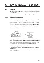
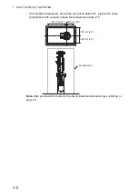


1. HOW TO INSTALL THE SYSTEM
1-9
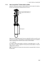
1.1.4
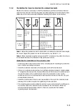
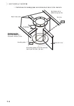
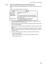
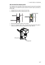
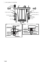
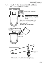
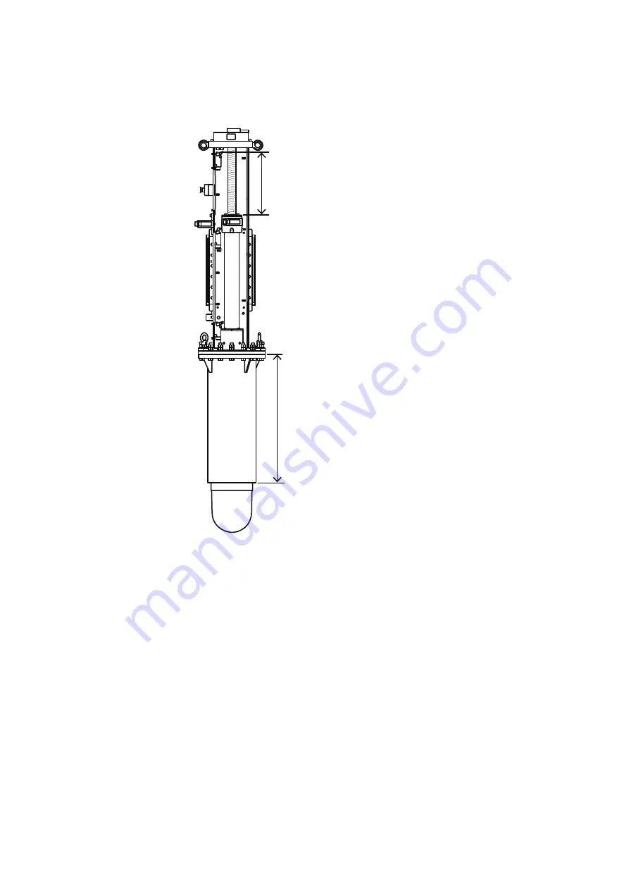
How to adjust the TX limit switch position
Adjust the TX limit switch position so that the switch is turned on where the transmit-
ting face of the transducer is projected from the hull unit.
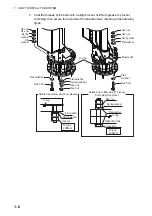
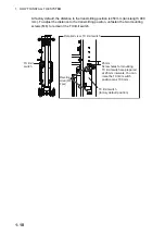
Distance to the transmitting position (A) can be selected from 450 mm, 425 mm, 400
mm, 375 mm or 350 mm. The distance to the transmitting position can be calculated
with the following formula. Select the value closest to the calculation.
• A = T- 450 mm
For example, when the tank length (T) is 820 mm, the calculated value is “ A = 820 -
450 = 370 mm”. Therefore, adjust the TX limit switch so that the distance to the trans-
mitting position is 375 mm.
Note:
The transducer can transmit when the transducer is projected 300 mm from the
retraction tank.
Tank length (T)
Distance to the transmitting position
䠄
A
䠅䠖
450 mm, 425 mm, 400 mm
㻘㻌
375 mm or
350 mm
Summary of Contents for FSV-85-MARK-2
Page 34: ...1 HOW TO INSTALL THE SYSTEM 1 26 This page is intentionally left blank ...
Page 58: ...2 WIRING 2 24 This page is intentionally left blank ...
Page 86: ...D 1 7 Jul 2021 H MAKI ...
Page 87: ...D 2 7 Jul 2021 H MAKI ...
Page 88: ...D 3 7 Jul 2021 H MAKI ...
Page 89: ...D 4 7 Jul 2021 H MAKI ...
Page 90: ...D 5 7 Jul 2021 H MAKI ...
Page 91: ...D 6 7 Jul 2021 H MAKI ...
Page 92: ...22 Apr 2014 H MAKI D 7 ...
Page 93: ...D 8 24 Jun 2021 H MAKI ...
Page 94: ...D 9 24 Mar 2021 H MAKI ...
Page 95: ...D 10 24 Jun 2021 H MAKI ...
Page 96: ...D 11 24 Jun 2021 H MAKI ...
Page 98: ...D 13 17 Feb 2021 H MAKI ...
Page 99: ...28 Apr 2018 H MAKI D 14 ...
Page 100: ...D 15 13 Sep 2011 Y NISHIYAMA ...
Page 101: ...D 16 13 Sep 2011 Y NISHIYAMA ...
Page 102: ...D 17 13 Sep 2011 Y NISHIYAMA ...


