background image

The paper used in this manual
is elemental chlorine free.

・FURUNO Authorized Distributor/Dealer

9-52 Ashihara-cho,
Nishinomiya, 662-8580, JAPAN

A : JUL

2021

.

Printed in Japan

All rights reserved.

Pub. No. IME-13670-A

(TEHI )

FSV-85-MARK-2-70/80

 0 0 0 1 9 8 9 0 4 1 0

Summary of Contents for FSV-85-MARK-2

Page 1: ... Use the Crimping Tool Pin Extractor 2 1 2 2 How to Connect Units 2 2 2 3 Processor Unit 2 5 2 4 Control Unit 2 11 2 5 Transceiver Unit 2 12 2 6 Raise Lower Control Box 2 16 2 7 Control Box Extension Box 2 18 3 ADJUSTMENTS AND CHECKS 3 1 3 1 How to Access the System Menu 3 1 3 2 How to Change the Displayed Language 3 1 3 3 Selecting Monitor Resolution 3 2 3 4 How to Set Up for Two Monitors 3 3 3 5...

Page 2: ...nual is elemental chlorine free FURUNO Authorized Distributor Dealer 9 52 Ashihara cho Nishinomiya 662 8580 JAPAN A JUL 2021 Printed in Japan All rights reserved Pub No IME 13670 A TEHI FSV 85 MARK 2 70 80 0 0 0 1 9 8 9 0 4 1 0 ...

Page 3: ...Turn off the power at the mains switchboard before beginning the installation Fire electrical shock or serious injury can result if the power is left on or is applied while the equipment is being installed Do not install the equipment where it may get wet from rain or water splash Water can cause fire or electrical shock or damage the equipment Be sure no water leaks in at the hull unit Water leak...

Page 4: ... vomiting can result Keep the oil out of reach of children For further details see the material safety data sheet MSDS Emergency If the oil enters eyes flush with clean water for about 15 min Consult a physician If the oil contacts skin wash with soap and water If the oil is ingested see a physician immediately Keep the oil out of reach of children For other information see the safety data sheet S...

Page 5: ...t 䠄80kHz䠅 FSV 8471 MK2 FSV 8472 MK2 FSV 8481 MK2 FSV 8482 MK2 Transceiver Unit FSV 851C MK2 200 220 VAC 3I 50 60 Hz 100 110 115 220 230 VAC 1I 50 60 Hz 䠖 Use the optional Control Box Extension Box FSV 2560 to extend the distance between the raise lower control box and the hull unit Raise Lower Control Box FSV 8520 MK2 Processor Unit FSV 8503 MK2 100 230 VAC 1ø 50 60 Hz AC DC Power Supply Unit PR 2...

Page 6: ...Transducer FSV 8422 MK2 FSV 8423 MK2 Frequency 80 kHz Dome Yes thickness 8mm No Nameplate Yes Unit type and serial no Color of binding tape Yellow Cable fabrication label Yes Unit name and serial no Color of unit Black Dome label Yes Dome flange stamping No ...

Page 7: ...800 travel 80 kHz less dome FSV 8481 MK2 1100 travel 80 kHz with dome FSV 8482 MK2 1100 travel 80 kHz less dome Installation Materials CP10 06000 000 067 071 1 CP10 09600 000 036 274 1 For Control Unit CP10 09700 000 036 275 1 For Processor Unit CP10 07011 001 005 660 1 For Transceiver Unit Spare Parts SP26 00301 001 080 860 1 For Processor Unit SP10 03101 007 008 530 1 For Transceiver Unit SP10 0...

Page 8: ... 450 For PR 241 5 Pair Cable 10S2380 10M 001 196 330 10 For between the processor unit and the transceiver 10 m 10S2380 20M 001 196 340 10 20 m 10S2380 30M 001 196 350 10 30 m 10S2380 40M 001 196 360 10 40 m 10S2380 50M 001 196 370 10 50 m 10S2380 60M 001 196 380 10 60 m 10S2380 100M 001 196 390 10 100 m Cable Assembly HDMI TO DVI L 5 3M 001 407 180 DVI HDMI cable 5 3 m HDMI TO DVI L 10 3M 001 407...

Page 9: ... with off the keel If the hull unit can not be installed on the keel the center of the retraction tank should be within 600 mm from the keel to prevent a rolling effect For large ship with deep draft the hull unit can be installed at the bow Select a place where the hull bottom is flat and the draft is sufficiently deep Normal ly the transducer should protrude at least 500 mm beyond the keel to mi...

Page 10: ...around the unit will be below 0 C provide the sonar compartment with a heater to keep the temperature above 0 C Note After you mount the hull unit be sure to install anti vibration stays referring to page 1 5 1200 mm 48 Compartment 500 mm 20 500 mm 20 500 mm 20 ...

Page 11: ...rsect If there is no suitable location where the hull frame and keel intersect install suitable T shaped reinforcement ribs then weld the base of the frame to the reinforcement ribs and the sides of the reinforcement ribs to the hull walls or other nearby reinforcement ribs The reinforcement ribs should be secured in the fore aft port and starboard directions Install the reinforcement ribs as near...

Page 12: ...ement ribs is 12 mm minimum Reinforcement ribs No of ribs Minimum 4 Thickness at least 12 mm 150 200mm Reinforcement rib added along keel line Keel line Doubling plate Bow Stern Fit doubling plates where the retraction tank meets the frame and keel Ship s framework Minimum 12 mm ...

Page 13: ...ribed on its flange points toward the ship s bow Note If the bow mark on the hull unit flange is not facing the ship s bow rotate the transducer so that the bow mark on the transducer points toward the ship s bow see section 3 9 4 Confirm the following points then place the hull unit on the retraction tank Clean the flange platform Wipe the undersurface of the hull unit flange with clean waste clo...

Page 14: ...e Hex nut Hex nut Spring washer Flat washer O ring Flat washer Hex bolt Hex nut Hex nut Spring washer Flat washer Detailed view Bow side Four places O ring Flat washer Spring washer Hex nut O ring Flat washer Spring washer Hex nut Hex bolt Retraction tank Flat washer Hex bolt Detailed view Bow side 11 places Stern side One place Hex nut Hex nut Spring wash Flat washer Bow mark Torque 230N m Torque...

Page 15: ...n the port side 1 Unfasten the four screws to remove the box base 2 Unfasten the two screws to remove the box cover 3 Remount the emergency switch to the port side 4 Secure the emergency switch cable using the three wiring bands Wiring band must be secured to the hull unit using pan head screws M4 12 Screw 4 pcs Emergency switch Box base Box base Box cover Box cover Screw 2 pcs Box base rear side ...

Page 16: ...in the port and one in the starboard direction making a total of four stays Where the hull unit is installed off center from the bow stern line install the stays at right angles with the bow mark on the hull unit Where horizontal installation of the stays is not possible install the stays in a diagonal manner to reduce vibration in the hull unit Bow mark Stay Recommended stay installation Eye bolt...

Page 17: ...0 mm The distance to the transmitting position can be calculated with the following formula Select the value closest to the calculation A T 450 mm For example when the tank length T is 820 mm the calculated value is A 820 450 370 mm Therefore adjust the TX limit switch so that the distance to the trans mitting position is 375 mm Note The transducer can transmit when the transducer is projected 300...

Page 18: ...nce to the transmitting position unfasten the two mounting screws M6 to remount the TX limit switch TX limit switch Detailed view TX limit switch 25 mm Screw holes for mounting TX limit switch are prepared at 25 mm intervals You can raise the TX limit switch position max 100 mm TX limit switch factory default position Mounting screw M6 2 pcs ...

Page 19: ...nough to support the weight of the unit Referring to the outline drawings at the back of this manual allow sufficient space for maintenance and service A magnetic compass will be affected if the unit is placed too close to the magnetic compass Observe the compass safe distances at the front of this manual to prevent interference to a magnetic compass For the bulkhead installations secure the unit ...

Page 20: ...ing with KB fixture The unit is secured from the topside Flush mounting Mounting considerations Select a location where the unit can easily be operated Locate the unit out of direct sunlight Locate the unit away from places subject to water splash and rain Select a location where shock and vibration are minimal Select a mounting location considering the length of the cable Referring to the outline...

Page 21: ...nd wire with the ship s ground 3 Insert four stud bolts M4 20 supplied to the bolt holes at the bottom of the unit Note Insert the stud bolts manually Do not use a tool to insert the bolts the unit may become damaged 4 Set the unit to the mounting location so that the stud bolts on the bottom of the unit are inserted to the pilot holes Note Be careful to prevent the ground wire from being caught b...

Page 22: ...gle 1 Drill four pilot holes in the mounting location for mounting screws referring to the outline drawing at the back of this manual 2 Secure the KB fixture supplied to the mounting location using four self tapping screws φ5 20 supplied Note Secure the KB fixture so that the cutout is located on the side farthest from the operator Wing nut 4 pcs Self tapping screw Ø5 20 4 pcs KB fixture Cutout sh...

Page 23: ... unit the KB fixture using four binding screws M5 20 sup plied 5 Attach four bolt hole caps supplied 1 3 3 Flush mounting Note Be sure the mounting surface is flat 1 Referring to the outline drawing at the back of this manual prepare a cutout then drill four pilot holes in the mounting location Ground wire Use the screw that is preattached to the ground terminal Ground screw Binding screw M5 20 4 ...

Page 24: ...then connect the other end of the ground wire with the ship s ground 3 Set the unit to the cutout then secure the unit with four self tapping screws φ5 20 supplied 4 Attach four bolt hole caps supplied Ground wire Use the screw that is preattached to the ground terminal Ground screw Bolt hole cap 4 pcs Self tapping screw Ø5 20 4 pcs ...

Page 25: ...ld be fixed to a mounting base shipyard supply whose dimensions are as shown in the outline drawing at the back of this manual Reinforce the transceiver unit against vibration by stays extending from the eye bolts on the top of the unit Fasten four bolts M12 local supply at the bottom of the transceiver unit to fix the unit to the mounting base ...

Page 26: ...n only be installed on a bulkhead Use 4 M10 bolts to fasten the raise lower control box in po sition The internal electromagnetic switches only function correctly if the raise lower control box is installed in the correct orientation as shown in the figure below Note 1 When installing the inertial mea surement unit inside the raise lower con trol box you must enter the location and angle of the ra...

Page 27: ...oints toward the ship s bow Note that heading adjustment in the monitor is required if the bow mark does not physically face the ship s bow 4 Confirm the following points as below and place the hull unit on the tank Clean the flange platform Wipe the undersurface of the hull unit flange with clean waste cloths Keep O ring in its groove 5 Insert the flat washers and insulation gaskets 2 into the bo...

Page 28: ...her O ring Insulation gasket 1 Insulation gasket 2 Flat washer Hex bolt O ring Insulation gasket 1 Insulation gasket 2 Flat washer Spring washer Hex bolt O ring RETRACTION TANK Flat washer Hex bolt Hex bolt Spring washer Flat washer Hex bolt O ring Insulation gasket 1 Insulation gasket 2 Spring washer Insulation gasket 1 Insulation gasket 2 ...

Page 29: ...ough hole Tape plug with sealing tape and replace it firmly SOCKET PLUG Set spout on container to dome opening and pour If antifreeze does not flow smoothly unplug air stopcock to let out air Pour in about 3 4 liters Antifreeze is visible from socket plug hole IF THERE IS NOT ENOUGH ROOM USE FUNNEL Funnel I12 13 Hose WHEN SHIP IS DRY DOCKED Filler hole is in high position NOTICE When the ship is d...

Page 30: ...lange with ethyl alcohol moistened waste cloths 2 Apply approx 1 mm thickness of liquid gasket TB1121 or TB1184 to the retrac tion tank flange For the application area see the following figure 3 Lay the waterproofing gasket on the tank flange Note 1 Do not apply liquid gasket to the waterproofing gasket If applied clean the gasket with waste cloth Note 2 Use only specified waterproofing gasket 4 P...

Page 31: ...g Insert the bolts with washers from the retraction tank flange and then put the flat washers and spring washers in this order from above Fasten bolts with nuts Bolt hole 㻮㻻㼃㻌㻹㼍㼞㼗 Insulation gasket Detail for fixing BOW 4 pcs Flat washer Spring washer Hex nut Detail for fixing BOW 11 pcs STERN 1 pc Hex nut Spring washer Flat washer Insulation gasket RETRACTION TANK Hex bolt Hex nut Hex nut Spring ...

Page 32: ...gs at the back of this manual allow sufficient space for maintenance and service A magnetic compass will be affected if the unit is placed too close to the magnetic compass Observe the compass safe distances at the front of this manual to prevent interference to a magnetic compass For flush installations select a location where the surface is flat 1 10 1 Desktop installation with keyboard fixture ...

Page 33: ...rol unit 1 Prepare a cutout in the mounting location referring to the outline drawing at the back of this manual 2 Set the unit to the cutout 3 Attach the mounting plate to the unit with four screws from the rear side 4 Screw the wing screw to each mounting plate and then insert hex bolt to each wing screw 5 Fasten each wing screw and then fasten the hex nuts Name Type Code No Qty Mounting plate 0...

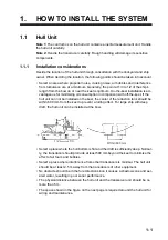
Page 34: ...1 HOW TO INSTALL THE SYSTEM 1 26 This page is intentionally left blank ...

Page 35: ... squeeze the handle until the ratchet releases The wire should be placed deep enough into the contact pin so that its end comes in con tact with the stopper plate of the crimping tool 4 With crimping completed pull the wire while holding the contact pin to make sure that the wire is held firmly by the contact pin 2 1 2 How to use the pin extractor If a contact pin is inserted into an incorrect hol...

Page 36: ...FSV 854 MK 2 Control Unit FSV 8501 MK 2 Sub Control Unit FSV 853 12 24 VDC 100 230 VAC 1ø 50 60 Hz AC DC Power Supply Unit PR 241 Transceiver Unit FSV 851C MK2 100 110 115 220 230 VAC 1ø 50 60 Hz Standard supply Optional or local supply 䠖 Use the optional Control Box Extension Box FSV 2560 to extend the distance between the raise lower control box and the hull unit 200 220 VAC 3ø 50 60 Hz Raise Lo...

Page 37: ... unit re attach the transducer and route the transducer cables as shown in the following fig ure Transducer cable 10S2320 16 pcs Cable clamp Cable securing plate Max 150 mm 100 mm Max 150 mm 100 mm 340 mm Transducer cable routing layout View from A Cable tie CV 350N Cable clamp 2 2 pcs Cable clamp 1 2 pcs Cable fixing rubber 6 pcs 㸿 2 1 Inside Outside Cable length 1100 mm travel 1 2 1020 mm 870mm ...

Page 38: ...1 Use three screws to secure one cable clamp How to attach the cable fixing rubber Outside routing cable Inside routing cable Slit Note The distance between inside and outside routing cable must be 30 to 40 mm at the location indicated in the figure on the previous page Also the distance between the flange and outside routing cable must be 100 to 120 mm Attach two cable routing rubber at the regul...

Page 39: ...DMI to be connected USB2 0 LAN2 SPEAKER To Speaker SEM 21Q 12 24 VDC Not used LAN1 To Transceiver Unit Note Use LAN1 port for connection with the Trans ceiver Unit HDMI2 To Monitor Unit Sub HDMI1 To Monitor Unit Main USB4 2 USB3 0 USB2 2 USB3 2 USB1 2 USB3 0 USB2 0 POWER To ship s ground Ground Terminal Cable entrance HDMI TO DVI L 5 3 10 3 m USB cable DTIC5E350SLABVCVxxT 1 Max 100 m USB cable MJ ...

Page 40: ...A0183 equipment TT P YCSLA 1Q 1 2 TB4 3 TB5 4 TB6 5 TB7 6 TB10 Transceiver unit 10S2380 1 7 TB2 Gyrocompass AD 10 TT P YCSLA 1Q 1 8 J1 Control unit 9 J2 Control unit 10 TB1 Remote controller external switch 2 11 TB8 External KP 3 TT P YCSLA 1 1 12 TB9 Not used 1 2 3 4 5 11 12 6 7 8 9 10 TB3 TB4 TB10 TB5 TB2 TB6 J1 TB7 J2 TB8 TB1 TB9 Secure each cable to the wiring clamp Terminal opener Cable clamp...

Page 41: ...or Unit side Transceiver Unit side Vinyl tape 35 䡉䡉 35 䡉䡉 Outer sheath Armor Inner sheath Shield Vinyl tape Cores Vinyl tape Clamp here Expose the cores then wind the shield around the inner sheath How to connect wires to a terminal connector Procedure 1 Twist the cores 2 Press the terminal opener downward 3 Insert the wire in the hole 4 Remove the terminal opener 5 Pull the wire to confirm that i...

Page 42: ...ful not to damage inner shield and cores Fold back the shield wrap it onto the inner vinyl sheath and cut it leaving approx 9 mm 25 mm approx 9 mm approx 9 mm approx 11 mm Fold back drain wire and cut it leaving approx 9 mm Straighten and flatten the cores in colored order and cut them leaving approx 11 mm Modular plug Using special crimping tool MPT5 8AS PANDUIT CORP crimp the modular plug Finall...

Page 43: ...p on lug FV1 25 3 supplied locally to the core Vinyl tape How to connect wires to a terminal connector Procedure 1 Twist the cores 2 Press the terminal opener downward 3 Insert the wire in the hole 4 Remove the terminal opener 5 Pull the wire to confirm that it is secure Press downward Terminal connector Terminal opener Twist Drain wire Drain wire Pass a heat shrinkable tube supplied locally onto ...

Page 44: ...y KP input To synchronize the KP Keying Pulse signal from external equipment make the con nection as follows When the external equipment is a current drive circuit Use the TB8 1 and TB8 2 When the external equipment is a voltage drive circuit Use the TB8 3 and TB8 4 The signals for current and voltage drive circuit cannot be used simultaneously REMOTE TB1 Processor Unit TILTUP_N TILTDN_N RANGUP_N ...

Page 45: ...nd voltage drive circuit can be used simultaneously for sep arate destinations 2 4 Control Unit Connect the control unit to the J1 or J2 terminal in the processor unit Ground the control unit using a ground wire IV 1 25sq supplied locally TB8 EXT_KP_H EXT_KP_C EXT_12V_KP GND INT_KP_H INT_KP_C INT_12V_KP GND 㻝 㻞 㻟 㻠 㻡 㻢 㻣 㻤 EXT KP P P KP signal Processor unit External equipment Current loop Externa...

Page 46: ...ard when the transducer cable is not connected lock the catch on the transducer cable connector HIF connector of that TRX board so that it won t contact the board release tab Hull Unit 10S2078 Processor Unit 10S2380 TB B101 CN B102 CN B101 Processor Unit DTIC5E350SLABVCVxxT CN B103 TRX 16 P2 64 pin P1 64 pin 1 2 3 4 5 6 7 8 9 10 11 12 13 14 15 16 Fix cables with clamps Fasten shield with steel cla...

Page 47: ...n tool Code No 10 910 0179 0 to correctly insert guide pins to connectors LAN cable Fabricate the cable referring to section 2 3 3 400 mm 400 mm 40 mm 40 mm 45 mm 45 mm Armor Anticorrosive sheath Vinyl Sheath Shield Expose cores then wind shield around armor Insulating tape Guide Pin A Guide Pin B Guide Pin B Small Guide Pin A Large Position No Guide pin Guide pin B small Guide pin A large 1 1 CN ...

Page 48: ...switch Fuses Change the fuse in F601 and F602 according to input voltage referring to the table below Input voltage S603 S604 S605 Default setting 100 VAC L L L 110 VAC H L L 115 VAC H H L 220 VAC H L H 230 VAC H H H Default Input Voltage TB B101 F601 F602 Default setting 100 VAC 20A 20A 110 VAC 115 VAC 220 VAC 10A 10A 230 VAC Default Anti corrosive sheath 140 mm 140 mm 30 mm 30 mm 35 mm 35 mm vin...

Page 49: ...itches and changing the fuses mark the label on the inside of the cover with the voltage that applies In the example shown in the figure to the right 100 V is checked 20A fuses are used FUSE FUSE F601 F602 INPUT TB B101 FUSE F601 F602 100V 110V 20A 20A 115V 220V 230V 10A 10A ...

Page 50: ...wer cables turn on the power and check if the LED lights The hull unit does not work when the connection is wrong Normal phase LED lights in red Phase reversal LED does not light Fabricate the power cable as shown below U V W Three phase AC TB C101 J2 Connect the transceiver cables 10CA10053 here LED for phase revesal 200 mm 200 mm 30 mm 30 mm Anti corrosive sheath Cores Crimp on lug FV2 4 2 pcs S...

Page 51: ...amp as shown below Connected to Hull unit or control box extension box 10CA10028 10CA10029 10CA10027 Wrap extension box installation materials DK020FR 19 on cable ends 10S2078 Transceiver unit FSV 851C D Emergency Stop button Shaft brake motor IV 8sq Grounding TPYCY 4 Ship s mains Limit Switch Limit Switch Rotary Encoder Rotary Encoder ...

Page 52: ...lace them with the included crimp on lugs See table below for details Connect the connectors to the control box extension box cables See the Interconnection Diagrams at the back of this manual for information on how to wire the raise lower control box and control box extension box Crimp on lug cable connections Note The orange line on the emergency stop button crimp with NCW 1 25 as follow ing fig...

Page 53: ... the raise lower control box must be installed in the control box extension box Fol low the procedure below How to remove the fans and inertial measurement unit from the raise lower control box 1 Unfasten six screws to remove the front cover 2 Unfasten four screws to remove the top cover 10S10027 10S10029 10S10028 Cables from hull unit LMT_SW Emergency stop button Shaft brake motor Cables from rai...

Page 54: ...l measurement unit then unfasten four screws to remove the unit 4 Disconnect the fan connectors then unfasten screws to remove two fans 5 Reattach the top cover and front cover Inertial measurement unit Remove the cable from this connector Fan Fan Remove these connectors ...

Page 55: ...possible install the unit after the control box extension box has been installed 1 Unfasten six screws to remove the front cover 2 Unfasten four screws to remove the top cover 3 Install the fans in the control box extension box using the four screws to secure them in place Top cover Front cover Control box extension box The metal fold on each fan case must face up Fan Fan Fan mounting direction ...

Page 56: ...e inertial measurement unit then fasten the screws to secure it 6 Connect the D SUB connector inside the control box extension box to the inertial measurement unit Connect the fan cable to the connector 2 locations Inertial measurement unit Rear side Inertial measurement unit Set the unit to the mounting screws then fasten the screws ...

Page 57: ...he ground wire crimp on lug of the D SUB cable to the ground terminal 8 Reattach the top cover and front cover Connect the D SUB cable to the inertial measurement unit Fasten the ground wire of the D SUB cable to this location ...

Page 58: ...2 WIRING 2 24 This page is intentionally left blank ...

Page 59: ... Press the MENU ESC key twice 5 Select Others then left click The System menu items are now displayed to the right side of the normal Others menu Repeating the above procedure will hide the System menu items 3 2 How to Change the Displayed Language The language in which the menus and indications are displayed can be changed This unit is shipped with the language set to English 1 Access the System ...

Page 60: ...n from Monitor Setting then left click 4 Left click SXGA UXGA or WUXGA as applicable SXGA 1280 1024 dots UXGA 1600 1200 dots WUXGA 1920 1200 dots 5 Select Quit in Monitor Setting menu then left click 6 Turn off and on the power then the resolution setting is reflected Note After changing the monitor resolution the size and display position of verti cal display will change Proceed with Monitor Sett...

Page 61: ... Display as applicable Dual Display When in dual mode each display can be assigned as Main or Sub monitor Sub Display Displays the same screen as the Main or Sub monitor When there is no secondary monitor set this option to OFF 5 Select Quit then left click 6 Close all menu windows then restart the FSV unit Caution This item is defined as non changeable item Are you sure to change it changeable Ch...

Page 62: ...ial Setting In the pop up window se lect Changeable 4 Select Vertical then left click 5 Select Quit then left click 6 Close all menu windows then restart the FSV unit 3 6 How to Change the Frequency Setting The default frequency is 80 kHz If the sonar frequency is 70 kHz an alarm sounds and a warning message appears the first time the power is applied after installation Change to 70 kHz as follows...

Page 63: ...he main menu 3 Select and left click in order Others Initial Setting In the pop up window se lect Changeable 4 Select Hull Unit Setting 5 Select REG TD Position The following confirmation message appears Note When the transducer position is already registered the following message appears To re register the transducer position select Next the left click 6 Confirm that transducer is retracted then ...

Page 64: ...his procedure How to enable transmission The default transmission state is OFF Enable transmission as shown in the procedure below NEVER transmit when the vessel is in dry dock to prevent damage to the transducer 1 Turn on the power and press the MENU ESC key to open the menu 2 Use the trackball to select Others then right click 3 Select Initial Setting then left click Registering Transducer Posit...

Page 65: ...ch to TEST Press the DOWN switch to confirm that the transducer lowers Also while the transducer is being lowered check that the HTX LED lights when the MD L SW kicks Note that the MD L SW does not stop the transducer when the TEST NOR MAL switch is in the TEST position 5 Press and release the DOWN switch during lowering Confirm that the transduc er stops lowering 6 Press the DOWN switch again to ...

Page 66: ... light when corresponding limit switch is kicked 2 The UP and DN LEDs light while UP and DOWN switches are pressed and ex tinguish when the switches are released 11 Set the TEST NORMAL switch to NORMAL 12 Check that the transducer is fully retracted At the control unit press the mid protrusion position switch Confirm that the LED above the switch blinks while the transducer is being lowered a shor...

Page 67: ... the heading alignment is cor rect If it does not measure the error and go to next step 3 If the heading is skewed measure the skew angle 4 Access the System menu referring to section 3 1 5 Select Others from the System menu items then left click 6 Select Heading Adjust 1 then left click 7 Rotate the scrollwheel to enter the angle measured at step 3 The setting range is 180 to 179 in one degree in...

Page 68: ...eft click 4 Use the scrollwheel to set length The setting range is 15 to 150 m 5 Set ship s width and transducer positions similarly Ship s Width The width of the ship at its widest point Setting range 5 to 30 m TD Position 1 Distance from transduc er to bow Setting range 5 to 50 m TD Position 2 Distance from transduc er to keel Select for starboard for port Setting range 10 to 10m 6 Long press th...

Page 69: ...e input format for speed data Disable GPS DR DOPPLER DR If response is slow select GPS Lat Lon Select the input format for position data Disable NMEA Water Depth Select the input format for water depth Disable NMEA Water Temp Select the input format for water temperature Disable NMEA Water Current Select the input format for water current Disable NMEA Wind Select the input format for wind data Dis...

Page 70: ...ange is 0 13 0 is OFF The higher the number the greater the suppression Propeller Tilt Keep the initial setting 0 When Propeller Supp above is set to 0 this item appears in gray Propeller Dir Set the bearing of the propeller as viewed from the transducer posi tion to set the bearing at which propeller noise is suppressed The setting range is 180 to 179 Exclus Apt Len Keep the initial setting 0 ...

Page 71: ...mm 19 5mm TTYCYSLA 1 0 75mm2 1 11mm 11 2mm TTYCYSLA 4 0 75mm2 1 11mm 17 9mm TTPYCSLA 1 0 75mm2 1 11mm 9 2mm TTPYCSLA 1T 0 75mm2 1 11mm 9 8mm TTPYCSLA 1Q 0 75mm2 1 11mm 10 5mm TTPYCSLA 4 0 75mm2 1 11mm 15 3mm EX TTYCYSLA 4 MPYC 4 Designation type of twisted pairs Designation type of cores 1 3 4 5 6 1 2 3 4 Cables listed in the manual are usually shown as Japanese Industrial Standard JIS Use the fol...

Page 72: ...e section 2 5 2 Vibration and sound while raising lowering the transducer Confirm that abnormal vibration or noise is not generated from the hull unit while raising lowering the trans ducer Software setting check Language setting The language in which the menus and indications is changed as nec essary section 3 2 Transducer position registration The transducer position registration is completed se...

Page 73: ...ic graphic data display Change the display setting for the numeric graphic data display as ap propriate Operator s manual Function key setting Assign the function to the function keys as necessary Operator s manual Preset the horizontal mode ranges Preset the horizontal mode ranges as selected with the RANGE control as necessary Operator s manual Check point Reference Result ...

Page 74: ...㼀㻴㻌㻎㻖㻖㻎㻌㻵㻺㻰㻵㻯㻭㼀㻱㻿㻌㼀㻴㻱㻌㻯㻻㻰㻱㻌㻺㼁㻹㻮㻱㻾㻌㻻㻲㻌㻾㻱㻼㻾㻱㻿㻱㻺㼀㻭㼀㻵㼂㻱㻌㻹㻭㼀㻱㻾㻵㻭㻸㻚 䠄 ᅗ䛾ᑍἲ䛿䚸ཧ 䛷䛩䚹㻌㻌㻰㻵㻹㻱㻺㻿㻵㻻㻺㻿㻌㻵㻺㻌㻰㻾㻭㼃㻵㻺㻳㻌㻲㻻㻾㻌㻾㻱㻲㻱㻾㻱㻺㻯㻱㻌㻻㻺㻸㼅㻚䠅 A 1 9 㻲㻿㼂㻙㻤㻡㻜㻟㻙㻹㻷㻞 1 0 2 8 7 1 6 5 37 21 2 θ 4 7 㻭 㻯 㻷 㻵 㻺 㻳 㻸 㻵 㻿 㼀 㻼 ࣘࢽࢵࢺ 81 7 ไᚚ㒊 352 6625 81 7 69 0 ணഛရ 63 5 3 576 ணഛရ 63 5 3 576 63 ᕤ ᮦᩱ 167 7 21 0 7 5 6 㺗㺎㺪㺼㺷 ရ0 66 0 63 ᕤ ᮦᩱ 167 7 21 0 7 5 6 3 ᅗ 2 80 17 㺩㺋㺎㺛㺼 せ㡿 86 5 3 0 17 8 䠄 ᅗ䛾ᑍἲ䛿䚸ཧ 䛷䛩䚹㻌㻌㻰㻵㻹㻱㻺㻿㻵㻻㻺㻿㻌㻵㻺㻌㻰㻾㻭㼃㻵㻺㻳㻌㻲㻻㻾㻌㻾㻱㻲㻱㻾㻱...

Page 75: ...㻿㻵㻻㻺㻿㻌㻵㻺㻌㻰㻾㻭㼃㻵㻺㻳㻌㻲㻻㻾㻌㻾㻱㻲㻱㻾㻱㻺㻯㻱㻌㻻㻺㻸㼅㻚䠅 A 3 9 㻲㻿㼂㻙㻤㻠㻣㻖㻛㻤㻠㻤㻖㻛㻤㻡㻣㻖㻛㻤㻡㻤㻖㻙㻹㻷㻞㻙㼀 1 0 2 8 7 1 6 5 37 21 2 θ 4 7 㻭 㻯 㻷 㻵 㻺 㻳 㻸 㻵 㻿 㼀 㻼 ࣘࢽࢵࢺ 81 7 ୖୗ 8 81 7 69 7 ணഛရ 63 5 3 576 ணഛရ 63 5 3 576 63 ᆅ 㒊ရ 2 66 0 1 ࠉ3 576 ᆅ 㒊ရ ワ 2 66 0 3 576 203 7 6 7 69 7 ᆅ 㒊ရ ワ 2 66 0 3 576 203 7 6 7 69 7 ᕤ ᮦᩱ 167 7 21 0 7 5 6 ᕤ ᮦᩱ 167 7 21 0 7 5 6 3 ᅗ 2 80 17 ഛせ㡿 167 7 21 0 18 0 䡶㻙䢀䢚 ྕᮎᑿ䛾㼇㻖㻖㼉䛿䚸㑅ᢥရ䛾௦ 䡶䡬䢀䢚䜢 䛧䜎䛩䚹 㻯㻻㻰㻱㻌㻺㼁㻹㻮㻱㻾㻌㻱㻺㻰㻵㻺...

Page 76: ...㻯㻻㻰㻱㻌㻺㼁㻹㻮㻱㻾㻌㻱㻺㻰㻵㻺㻳㻌㼃㻵㼀㻴㻌㻎㻖㻖㻎㻌㻵㻺㻰㻵㻯㻭㼀㻱㻿㻌㼀㻴㻱㻌㻯㻻㻰㻱㻌㻺㼁㻹㻮㻱㻾㻌㻻㻲㻌㻾㻱㻼㻾㻱㻿㻱㻺㼀㻭㼀㻵㼂㻱㻌㻹㻭㼀㻱㻾㻵㻭㻸㻚 㻔㻖㻝㻕䛾 ᆅ 㒊ရ䛿 ᵝ䛻䜘䜚㑅ᢥ㢪䛔䜎䛩䚹 㻔㻖㻝㻕㻦㻯㻴㻻㻻㻿㻱㻌㻻㻺㻱㻌㻭㻯㻯㻻㻾㻰㻵㻺㻳㻌㼀㻻㻌㻿㻼㻱㻯㻵㻲㻵㻯㻭㼀㻵㻻㻺㻚 䠄 ᅗ䛾ᑍἲ䛿䚸ཧ 䛷䛩䚹㻌㻌㻰㻵㻹㻱㻺㻿㻵㻻㻺㻿㻌㻵㻺㻌㻰㻾㻭㼃㻵㻺㻳㻌㻲㻻㻾㻌㻾㻱㻲㻱㻾㻱㻺㻯㻱㻌㻻㻺㻸㼅㻚䠅 A 5 9 㻲㻿㼂㻙㻤㻡㻠㻙㻹㻷㻞㻙㻱㻙㻖 1 0 2 8 7 1 6 5 37 21 2 θ 4 7 㻭 㻯 㻷 㻵 㻺 㻳 㻸 㻵 㻿 㼀 㻼 ࣘࢽࢵࢺ 81 7 㺶㺱㺘㺻 5 027 21752 5 69 0 ᕤ ᮦᩱ 167 7 21 0 7 5 6 ᕤ ᮦᩱ 167 7 21 0 7 5 6 3 䡶㻙䢀䢚 ྕᮎᑿ䛾㼇㻖㻖㼉䛿䚸㑅ᢥရ䛾௦ 䡶䡬䢀䢚䜢 䛧䜎䛩䚹 㻯㻻㻰㻱㻌...

Page 77: ...㻺㻿㻌㻵㻺㻌㻰㻾㻭㼃㻵㻺㻳㻌㻲㻻㻾㻌㻾㻱㻲㻱㻾㻱㻺㻯㻱㻌㻻㻺㻸㼅㻚䠅 A 7 㧼 㧼 㧭㧯㧷㧵㧺㧳 ޓ 㧸㧵㧿㨀 8 58 0 1 7 6 0 5 4 26 10 1 ͳ 3 6 70 6 ᤃᠲ ㇱ 10641 70 6 58 Ꮏ ᢱ 056 6 10 6 4 5 Ꮏ ᢱ 056 6 10 6 4 5 2 䋨 䈱ኸᴺ䈲䇮ෳ ୯䈪䈜䇯㩷㩷㪛㪠㪤㪜㪥㪪㪠㪦㪥㪪㩷㪠㪥㩷㪛㪩㪘㪮㪠㪥㪞㩷㪝㪦㪩㩷㪩㪜㪝㪜㪩㪜㪥㪚㪜㩷㪦㪥㪣㪰㪅䋩 ဳᑼ㪆䍘䍎䍢䍼 ภ䈏䋲Ბ䈱႐ว䇮ਅᲑ䉋䉍 Ბ䈮ઍ䉒䉎ㆊᷰᦼຠ䈪䈅䉍䇮䈬䈤䉌䈎䈏 䈦䈩䈇䉁䈜䇯䇭䈭䈍䇮ຠ 䈲ᄌ䉒䉍䉁䈞䉖䇯 㪫㪮㪦㩷㪫㪰㪧㪜㪪㩷㪘㪥㪛㩷㪚㪦㪛㪜㪪㩷㪤㪘㪰㩷㪙㪜㩷㪣㪠㪪㪫㪜㪛㩷㪝㪦㪩㩷㪘㪥㩷㪠㪫㪜㪤㪅㩷㩷㪫㪟㪜㩷㪣㪦㪮㪜㪩㩷㪧㪩㪦㪛㪬㪚㪫㩷㪤㪘㪰㩷㪙㪜㩷㪪㪟㪠㪧㪧㪜㪛㩷㪠㪥㩷㪧㪣㪘㪚㪜㩷㪦㪝㩷㪫㪟㪜㩷㪬㪧㪧㪜㪩㩷 㪧㪩㪦㪛㪬㪚㪫㪅㩷㪨㪬㪘㪣㪠㪫㪰㩷㪠㪪㩷㪫㪟㪜...

Page 78: ...ᦼຠߢ ࠅ ޔ߅ߥޓޕߔ ߡߞ ߇߆ࠄߜߤޔ ຠ ߪᄌࠊࠅ ߖࠎ ޕ 691 6 2 5 0 1 5 56 14 0 6 6 19 4 241 7 6 5 22 0 2 1 6 722 4 241 7 6 37 6 5 6 5 A 9 2 12 7 3 3 ࠉࠉᅗ 287 1 ྡࠉࠉ 1 0 ᩘ㔞 4 7 㸭ഛ 5 0 5 6 ྕ 12 ᆺྡ㸭つ᱁ 6 5 37 216 167 7 21 0 7 5 6 ᕤ ᮦᩱ 㺦㺚㺼㺕㺊㺍㺪㺽 3 2 12 㺨㺼㺐㺻㺢㺼㺞㺍㺩㺽㺻 㺚㺋 7 33 1 6 5 686 2 12 ෭㛫ᅽ㐀 㺣㺍㺢 1 187 0 686 2 12 ᑍษ㺬㺼㺷㺢 7 5 52 0 686 2 12 㺨㺼㺐㺻㺢㺼㺘㺦㺚㺼 1 1 6 5 0 686 2 12 㸦 ᅗࡢᑍἲࡣࠊཧ ࡍࠋࠉ 0 16 216 1 5 1 25 5 5 1 21 㸧 㹄㹓㹐㹓㹌㹍ࠉ㹃㹊㹃㹁㹒㹐㹇㹁ࠉ...

Page 79: ...1 ྡࠉࠉ 1 0 ᩘ㔞 4 7 㸭ഛ 5 0 5 6 ྕ 12 ᆺྡ㸭つ᱁ 6 5 37 216 167 7 21 0 7 5 6 ᕤ ᮦᩱ 8 69 69 㺘㺦㺖㺞 㸧 211 725 9 2 12 స㺸㺨㺼㺎 7 50 1 23 1 5 2 12 㺘㺦㺖㺞 211 725 85 2 12 㺘㺻㺞㺖㺢㺩㺽㺻 217 7 3 1 2 12 ᅽ Ꮚ 5 03 21 8 9 8 2 12 㺏㺎㺛ᯈ 233 5 675 3 52 6 2 12 㸦 ᅗࡢᑍἲࡣࠊཧ ࡍࠋࠉ 0 16 216 1 5 1 25 5 5 1 21 㸧 㹄㹓㹐㹓㹌㹍ࠉ㹃㹊㹃㹁㹒㹐㹇㹁ࠉ㹁㹍ࠉ㸬㸪㹊㹒㹂 0 ဳ ဳ ᑼ 㩄㨺㩎㩨 ภ߇㧞Ბߩ႐ว ޔ ਅᲑࠃࠅ Ბߦઍࠊࠆㆊᷰᦼຠߢ ࠅ ޔ߅ߥޓޕߔ ߡߞ ߇߆ࠄߜߤޔ ຠ ߪᄌࠊࠅ ߖࠎ ޕ 691 6 2 5 0 1 5 56 14 0 6 6 19 4 241 7 6...

Page 80: ...ング O RING C0 0117A P355 1 000 158 976 10 9 CODE NO 略図の寸法は 参考値です DIMENSIONS IN DRAWING FOR REFERENCE ONLY FURUNO ELECTRIC CO LTD 0 A 13 C C ODE NO 001 520 130 00 TYPE FSV 85 85L T 略 図 OUTLINE 名 称 NAME 数量 Q TY 用途 備考 REMARKS 番 号 NO 型名 規格 DESCRIPTIONS 1 1 1 INSTALLATION MATERIALS 工事材料表 10CV X 9409 FSV 85 85L T Oリング O RING C0 0117A P355 1 000 158 976 10 1 CODE NO 圧着端子 CRIMP ON LUG FV5 5 4 LF YEL K 3 ...

Page 81: ...NSIONS IN DRAWING FOR REFERENCE ONLY FURUNO ELECTRIC CO LTD 0 A 15 C C ODE NO 001 520 100 00 TYPE FSV 85 85L D 略 図 OUTLINE 名 称 NAME 数量 Q TY 用途 備考 REMARKS 番 号 NO 型名 規格 DESCRIPTIONS 1 1 1 INSTALLATION MATERIALS 工事材料表 10CV X 9406 FSV 85 85L D ソナー不凍液 4L SONAR ANTIFREEZE FSV 84 84L 1 007 023 030 00 1 CODE NO 圧着端子 CRIMP ON LUG FV5 5 4 LF YEL K 3 000 166 744 11 2 CODE NO ハイセンバンド BAND HP 5N 3 000 162 50...

Page 82: ...数量 Q TY 用途 備考 REMARKS 番 号 NO 型名 規格 DESCRIPTIONS 1 1 3 INSTALLATION MATERIALS 工事材料表 10CO X 9408 FSV 24 24S ケーブル 組品 CABLE ASSY 10S2078 1 送受信装置 上下装置 000 144 389 00 1 CODE NO 10S2078 000 160 862 10 略図の寸法は 参考値です DIMENSIONS IN DRAWING FOR REFERENCE ONLY FURUNO ELECTRIC CO LTD 型式 コード番号が2段の場合 下段より上段に代わる過渡期品であり どちらかが入っています なお 品質は変わりません TWO TYPES AND CODES MAY BE LISTED FOR AN ITEM THE LOWER PRODUCT MAY B...

Page 83: ...ຠ ߪᄌࠊࠅ ߖ ࠎ ޕ 691 6 2 5 0 1 5 56 14 0 6 6 19 4 241 7 6 5 22 0 2 1 6 722 4 241 7 6 37 6 5 6 5 A 19 2 12 7 3 3 ࠉࠉᅗ 287 1 ྡࠉࠉ 1 0 ᩘ㔞 4 7 㸭ഛ 5 0 5 6 ྕ 12 ᆺྡ㸭つ᱁ 6 5 37 216 167 7 21 0 7 5 6 ᕤ ᮦᩱ ᑟ㟁ᛶᕸ㺡㺎㺪㺽 21 8 7 9 7 3 5 0 2 12 ᅽ Ꮚ 5 03 21 8 9 2 12 ᅽ Ꮚ 5 03 21 8 9 5 2 12 㺮㺔㺼㺕ᖹᗙ㔠 7 6 5 0 686 2 12 භゅ㺣㺍㺢ࠉ 㺚㺋 187 0 686 2 12 㺨㺼㺦ᗙ㔠 635 1 6 5 0 686 2 12 㺹㺍㺔㺖㺜㺯㺛 6 5 2 7 0 686 2 12 㸦 ᅗࡢᑍἲࡣࠊཧ ࡍࠋࠉ 0 16 216 1 5 1 25 5...

Page 84: ...ޓ 㧯㧻 ޓ 㧚㧘㧸㨀㧰 ဳᑼ 㩄㨺㩎㩨 ภ߇㧞Ბߩ႐ว ޔ ਅᲑࠃࠅ Ბߦઍࠊࠆㆊᷰᦼຠߢ ࠅ ޔ߅ߥޓޕߔ ߡߞ ߇߆ࠄߜߤޔ ຠ ߪᄌࠊࠅ ߖࠎ ޕ 691 6 2 5 0 1 5 56 14 0 6 6 19 4 241 7 6 5 22 0 2 1 6 722 4 241 7 6 37 6 5 6 5 A 21 2 12 7 3 63 7 0 12 1 0 2 3 3 57 287 1 12 25 3 5 6 6 7 3 5 9 9 6 63 5 25 1 48 17 7 5 0 5 6 2 12 2 12 3 6 3 12 63 5 3 576 67 25 8 6 6 76 3 5 9 9 66 7 3 12 㺩㺋㺎㺛㺼 2 9 3 66 78 86 㺩㺋㺎㺛㺼 2 9 3 66 78 86 0 5 6 1 0 85812 75 2 7 12 㸦 ᅗࡢᑍἲࡣࠊཧ ࡍࠋࠉ 0 1...

Page 85: ...㺎㺛㺼 2 9 3 ཷಙ 25 75 16 9 5 81 7 66 78 86 㺩㺋㺎㺛㺼 0 9 3 ཷಙ 25 75 16 9 5 81 7 66 78 86 0 5 6 1 0 85812 75 2 7 12 㸦 ᅗࡢᑍἲࡣࠊཧ ࡍࠋࠉ 0 16 216 1 5 1 ࠉ 25 5 5 1 21 㸧 3 A 23 2 12 7 3 63 7 0 12 1 0 2 3 3 57 287 1 12 25 3 5 6 6 7 3 5 9 9 6 63 5 25 1 48 17 7 5 0 5 6 2 12 2 12 3 6 3 12 63 5 3 576 67 25 8 6 6 76 3 5 9 9 66 7 3 12 㺩㺋㺎㺛㺼 0 9 3 86 66 78 7 3 㺩㺋㺎㺛㺼 0 9 3 66 78 86 0 5 6 1 0 85812 75 2 7 12 㸦 ᅗࡢᑍἲࡣࠊཧ ࡍࠋࠉ 0...

Page 86: ...D 1 7 Jul 2021 H MAKI ...

Page 87: ...D 2 7 Jul 2021 H MAKI ...

Page 88: ...D 3 7 Jul 2021 H MAKI ...

Page 89: ...D 4 7 Jul 2021 H MAKI ...

Page 90: ...D 5 7 Jul 2021 H MAKI ...

Page 91: ...D 6 7 Jul 2021 H MAKI ...

Page 92: ...22 Apr 2014 H MAKI D 7 ...

Page 93: ...D 8 24 Jun 2021 H MAKI ...

Page 94: ...D 9 24 Mar 2021 H MAKI ...

Page 95: ...D 10 24 Jun 2021 H MAKI ...

Page 96: ...D 11 24 Jun 2021 H MAKI ...

Page 97: ...7 二 ロ 表2 TABLE 2 注記 1 指定外の寸法公差は表1による ヶ王讐 10 NOTE 1 TABLE 1 INDICATES TOLERANCE OF DIMENSIONS vi廿ICH IS NOT SPECIFIED DRAVN 立5卑 翠闘脚碑L_ Cl CKED 25 Jun 2021廿 MAKI APPRllV D I I TITLE _ _ 后 SV 85 BSL MARK 2 1 S叩 D t li No 1 2 HASS表2参照 TABLE 2 C1367 G07 A 町 No 10 091 170G 1 SV 854 MK2 リモコソ 外寸図 暉 REMOTE CONTROLLER OUTLINE DRA JING FURUNO ELECTRIC CO LTD D 12 7 Jul 2021H MAKI ...

Page 98: ...D 13 17 Feb 2021 H MAKI ...

Page 99: ...28 Apr 2018 H MAKI D 14 ...

Page 100: ...D 15 13 Sep 2011 Y NISHIYAMA ...

Page 101: ...D 16 13 Sep 2011 Y NISHIYAMA ...

Page 102: ...D 17 13 Sep 2011 Y NISHIYAMA ...

Page 103: ... 1 1 1 1 1 9 VT 1 86 86 9 86 9 1 9 86 1 1 9 86 1 7 7B 3 7B 3 7B 9B 3 1 1 17B 3 17B 3 17B 9B 3 1 9 48 30 17 ἲ 7 7 5 5 1 1 10 㹼 7 㹼 3 3 3 86 86 B B1 86 B B3 86 B665 B1 86 B665 B3 86 B667 B1 86 B667 B3 86 B B1 86 B B3 86 B665 B1 86 B665 B3 86 B667 B1 86 B667 B3 7 3 5 027 7 7 783B1 7 7 1B1 5 1 83B1 5 1 1B1 183B1 5275B1 1 1B1 527 B1 B 0 1 ࢳࣕ ࢲ 㺮㺢㺼㺶 㺯㺵㺙㺕 ࣁ 51 5 25 51 8 33 5 5 6 59 B1 5 6 59 B1 5 6 59 B1...

Page 104: ... 2 69 㺚㺹 㺏㺓 㺚㺹 3 3 㺮㺢㺼㺶 7 8 7 㺚㺹 3 7 㺕 51 㺟㺊 51 51 51 5 25 㺟㺊 㺏㺔 㺮㺢㺼㺶 㺞㺼㺐 㺯㺵㺙㺕 33 㺕 㺏㺓 8 027 21 6 1625 3 7 51 7 7 8 51 㺮㺢㺼㺶 51 3 㺖㺹 㺮㺢㺼㺶 51 㺖㺹 㺕 㺏㺔 5 㺕 㺟㺊 51 3 3 51 㺟㺊 25 㺞㺼㺐 5 㺏㺔 㺕 㺏㺓 8 51 㺮㺢㺼㺶 51 㺟㺊 㺏㺔 5 㺟㺊 51 3 51 㺮㺢㺼㺶 㺕 㺕 51 㺮㺢㺼㺶 1 02725 0 5 1 5 㺏㺔 3 P 85 㺚㺹 㺏㺓 㺚㺹 3 3 㺮㺢㺼㺶 7 8 7 㺚㺹 3 7 㺚㺹 3 7 3 8 3 㺮㺢㺼㺶 3 㺕 㺟㺊 㺖㺹 㺖㺹 㺖㺹 㺕 㺏㺓 51 51 51 7 51 8 51 5 25 5 51 33 5 7 㺏㺓 㺟㺊 㺏㺔 㺕 㺏㺔 㺖㺹 㺟㺊 㺖㺹 㺚㺹 㺖㺹 㺮㺢㺼㺶 ...

Reviews: