


1. HOW TO INSTALL THE SYSTEM
1-14
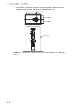
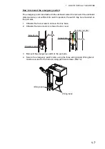
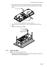
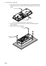
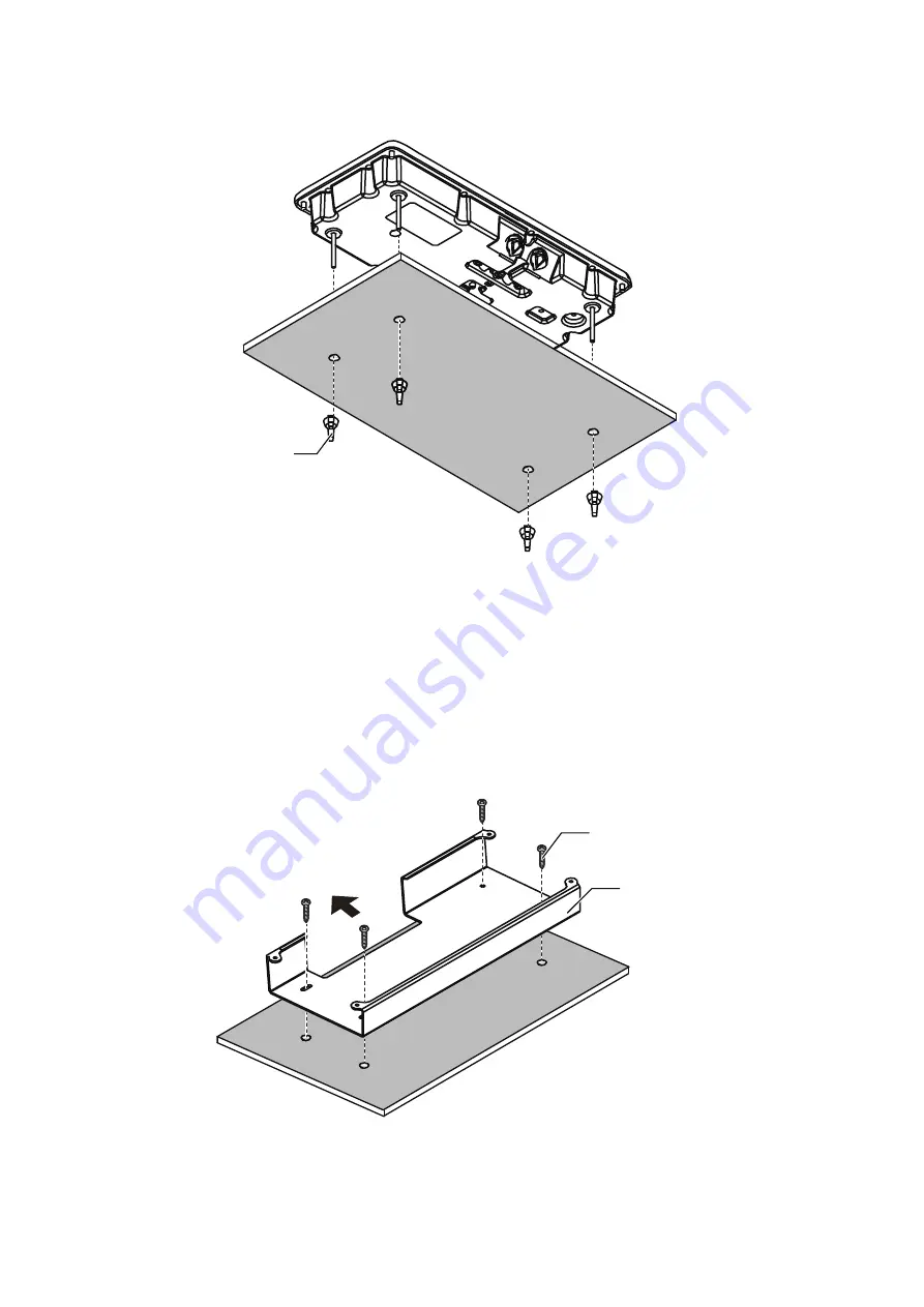
5. Fasten the four wing nuts (supplied) to the stud bolts from the rear side of the
mounting surface.
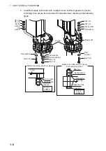
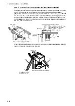
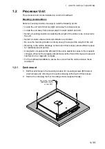
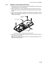
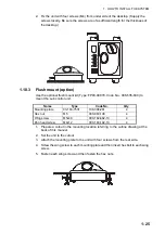
1.3.2
Tabletop mounting with KB fixture
The control unit can be mounted with the KB fixture, which mounts the unit at an angle.
1. Drill four pilot holes in the mounting location for mounting screws, referring to the
outline drawing at the back of this manual.
2. Secure the KB fixture (supplied) to the mounting location, using four self tapping
screws (
φ
5
×
20, supplied).
Note:
Secure the KB fixture so that the cutout is located on the side farthest from
the operator.
Wing nut
(4 pcs)
Self-tapping screw
(Ø5×20, 4 pcs)
KB fixture
Cutout should be located on
the side farthest from the
operator.
Summary of Contents for FSV-85-MARK-2
Page 34: ...1 HOW TO INSTALL THE SYSTEM 1 26 This page is intentionally left blank ...
Page 58: ...2 WIRING 2 24 This page is intentionally left blank ...
Page 86: ...D 1 7 Jul 2021 H MAKI ...
Page 87: ...D 2 7 Jul 2021 H MAKI ...
Page 88: ...D 3 7 Jul 2021 H MAKI ...
Page 89: ...D 4 7 Jul 2021 H MAKI ...
Page 90: ...D 5 7 Jul 2021 H MAKI ...
Page 91: ...D 6 7 Jul 2021 H MAKI ...
Page 92: ...22 Apr 2014 H MAKI D 7 ...
Page 93: ...D 8 24 Jun 2021 H MAKI ...
Page 94: ...D 9 24 Mar 2021 H MAKI ...
Page 95: ...D 10 24 Jun 2021 H MAKI ...
Page 96: ...D 11 24 Jun 2021 H MAKI ...
Page 98: ...D 13 17 Feb 2021 H MAKI ...
Page 99: ...28 Apr 2018 H MAKI D 14 ...
Page 100: ...D 15 13 Sep 2011 Y NISHIYAMA ...
Page 101: ...D 16 13 Sep 2011 Y NISHIYAMA ...
Page 102: ...D 17 13 Sep 2011 Y NISHIYAMA ...