


1. HOW TO INSTALL THE SYSTEM
1-25
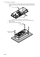
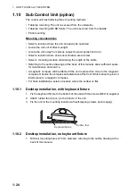
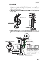
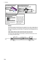
2. Fix the unit with four screws (M4) from under side of the desktop. (Supply the
screws locally. Be sure the screws are of a sufficient length for the thickness of
the desktop.)
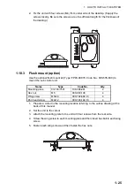
1.10.3
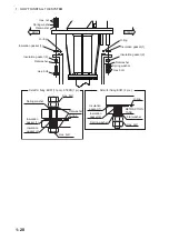
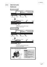
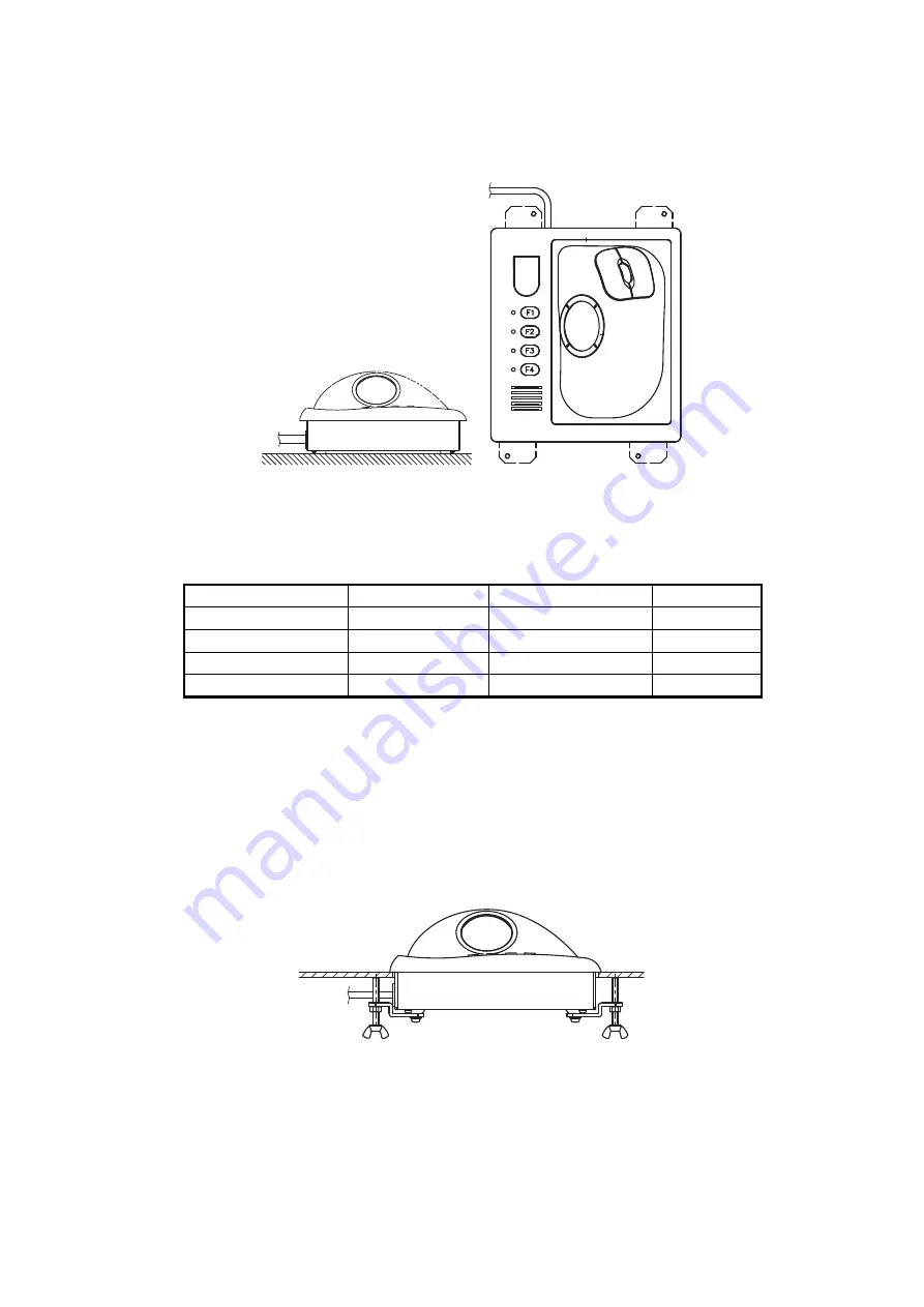
Flush mount (option)
Use the optional flush mount kit (Type: FP03-09870, Code No.: 008-535-630) to
mount the sub control unit.
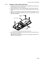
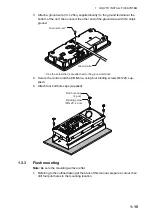
1. Prepare a cutout in the mounting location referring to the outline drawing at the
back of this manual.
2. Set the unit to the cutout.
3. Attach the mounting plate to the unit with four screws from the rear side.
4. Screw the wing screw to each mounting plate and then insert hex bolt to each wing
screw.
5. Fasten each wing screw and then fasten the hex nuts.
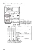
Name
Type
Code No.
Qty
Mounting plate
03-163-7531
100-306-261
4
Hex nut
M5
000-863-108
4
Wing screw
M5x40
000-162-682-10
4
Pan head screw
M4x12
000-163-192-10
4
Summary of Contents for FSV-85-MARK-2
Page 34: ...1 HOW TO INSTALL THE SYSTEM 1 26 This page is intentionally left blank ...
Page 58: ...2 WIRING 2 24 This page is intentionally left blank ...
Page 86: ...D 1 7 Jul 2021 H MAKI ...
Page 87: ...D 2 7 Jul 2021 H MAKI ...
Page 88: ...D 3 7 Jul 2021 H MAKI ...
Page 89: ...D 4 7 Jul 2021 H MAKI ...
Page 90: ...D 5 7 Jul 2021 H MAKI ...
Page 91: ...D 6 7 Jul 2021 H MAKI ...
Page 92: ...22 Apr 2014 H MAKI D 7 ...
Page 93: ...D 8 24 Jun 2021 H MAKI ...
Page 94: ...D 9 24 Mar 2021 H MAKI ...
Page 95: ...D 10 24 Jun 2021 H MAKI ...
Page 96: ...D 11 24 Jun 2021 H MAKI ...
Page 98: ...D 13 17 Feb 2021 H MAKI ...
Page 99: ...28 Apr 2018 H MAKI D 14 ...
Page 100: ...D 15 13 Sep 2011 Y NISHIYAMA ...
Page 101: ...D 16 13 Sep 2011 Y NISHIYAMA ...
Page 102: ...D 17 13 Sep 2011 Y NISHIYAMA ...


