


2. WIRING
2-19
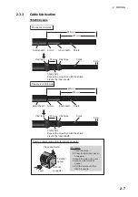
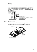
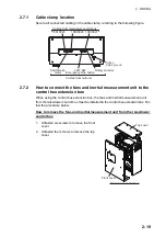
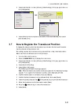
2.7.1
Cable clamp location
Secure all connected cabling in the cable clamp, referring to the following figure.
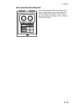
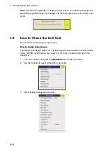
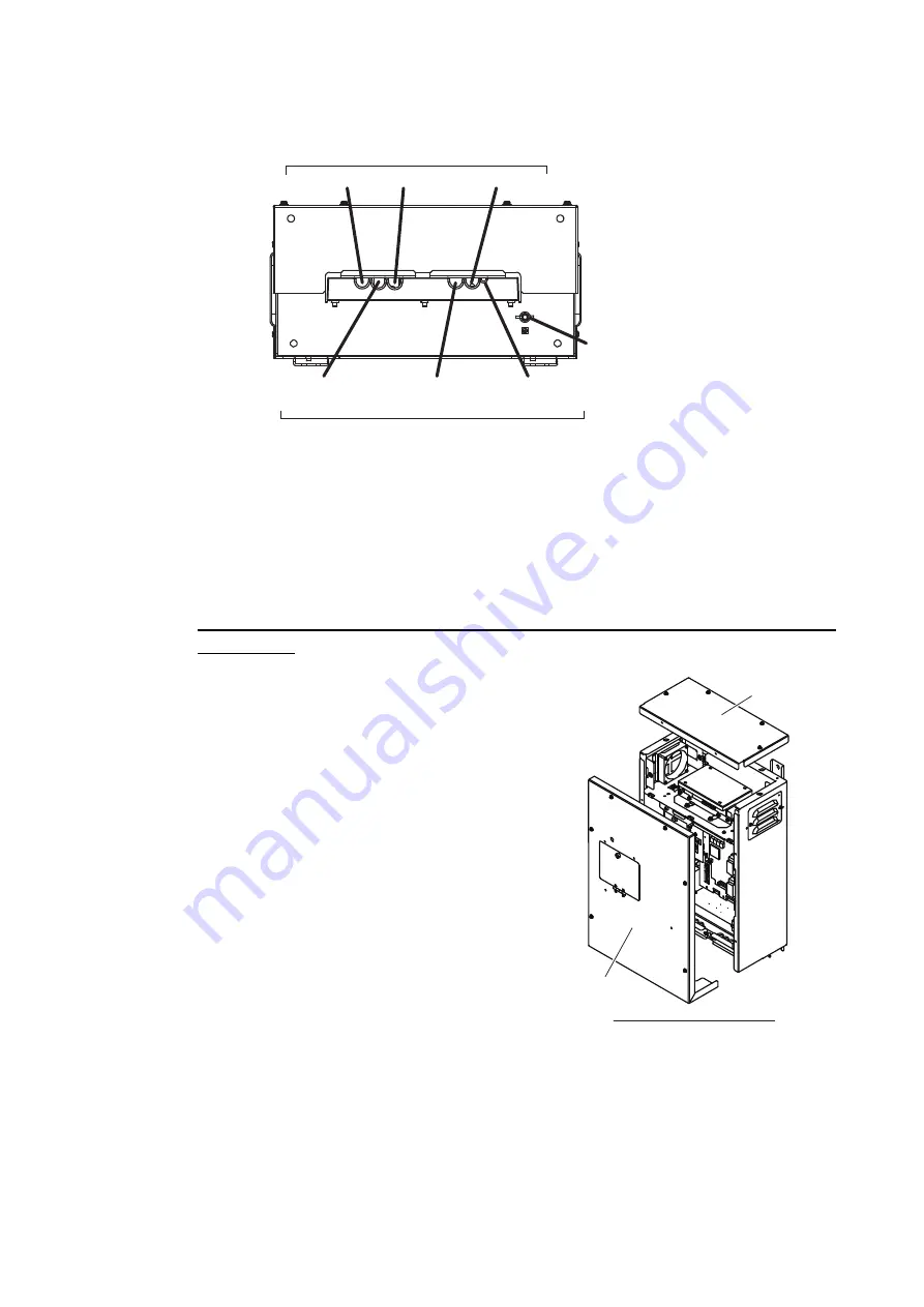
2.7.2
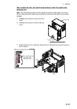
How to connect the fans and inertial measurement unit to the
control box extension box
When using the control box extension box, the fans and inertial measurement unit
from the raise/lower control box must be installed in the control box extension box. Fol-
low the procedure below.
How to remove the fans and inertial measurement unit from the raise/lower
control box
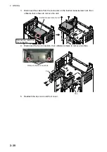
1. Unfasten six screws to remove the front
cover.
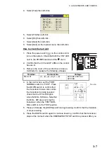
2. Unfasten four screws to remove the top
cover.
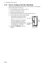
10S10027
10S10029
10S10028
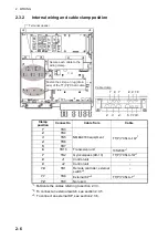
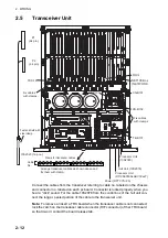
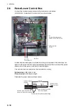
Cables from hull unit
LMT_SW
Emergency stop button
Shaft brake
motor
Cables from raise/lower control box
Rotary encoder
IV-8sq
Ship's ground
Top cover
Raise/lower control box
Front cover
Summary of Contents for FSV-85-MARK-2
Page 34: ...1 HOW TO INSTALL THE SYSTEM 1 26 This page is intentionally left blank ...
Page 58: ...2 WIRING 2 24 This page is intentionally left blank ...
Page 86: ...D 1 7 Jul 2021 H MAKI ...
Page 87: ...D 2 7 Jul 2021 H MAKI ...
Page 88: ...D 3 7 Jul 2021 H MAKI ...
Page 89: ...D 4 7 Jul 2021 H MAKI ...
Page 90: ...D 5 7 Jul 2021 H MAKI ...
Page 91: ...D 6 7 Jul 2021 H MAKI ...
Page 92: ...22 Apr 2014 H MAKI D 7 ...
Page 93: ...D 8 24 Jun 2021 H MAKI ...
Page 94: ...D 9 24 Mar 2021 H MAKI ...
Page 95: ...D 10 24 Jun 2021 H MAKI ...
Page 96: ...D 11 24 Jun 2021 H MAKI ...
Page 98: ...D 13 17 Feb 2021 H MAKI ...
Page 99: ...28 Apr 2018 H MAKI D 14 ...
Page 100: ...D 15 13 Sep 2011 Y NISHIYAMA ...
Page 101: ...D 16 13 Sep 2011 Y NISHIYAMA ...
Page 102: ...D 17 13 Sep 2011 Y NISHIYAMA ...


