background image

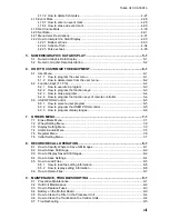
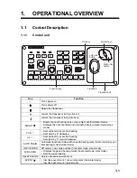
1.  OPERATIONAL OVERVIEW

1-6

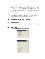
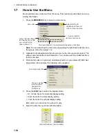
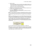
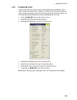
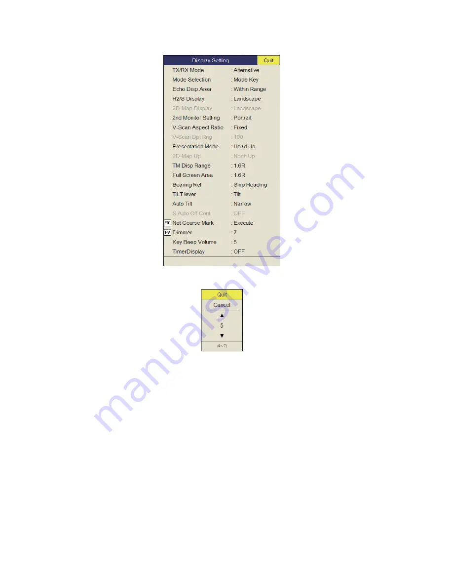
3. Select [Display Setting] then push the left-click button.

4. Select [Dimmer] then push the left-click button to show the setting box.

5. Select 

S

 (increase) or 

T

 (decrease).

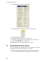
6. Push the left-click button several times to select a value.
7. Select [Quit] on the setting box then push the left-click button to close the box.
8. Long-press the 

MENU/ESC

 key to close all menus.

Note: 

The default function of the 

F8

 key adjusts the panel dimmer.
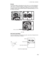
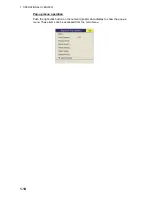
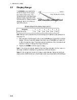
1.5

Display Mode, Display Division

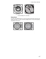
There are six display modes; Horizontal, Horiz Horizontal2*, Slant (single dis-
play), Hori Slant*, Vertical1* and Vertical 1 + Vertical 2*.

*: If the FSV-85 is fitted with dual monitors, you can select how the picture data is 

shown on two displays; Dual Display or Sub Display. For details, see page 7-8.

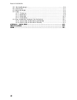
Summary of Contents for FSV-85

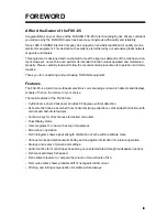
Page 1: ...COLOR SCANNING SONAR FSV 85 OPERATOR S MANUAL www furuno com Model ...

Page 2: ...tal chlorine free FURUNO Authorized Distributor Dealer 9 52 Ashihara cho Nishinomiya 662 8580 JAPAN A MAR 2011 Printed in Japan All rights reserved B1 FEB 07 2013 Pub No OME 13350 B1 00017433911 ETMI FSV 85 00017433911 0 0 0 1 7 4 3 3 9 1 1 ...

Page 3: ...is product according to local regulations for the disposal of industrial waste For disposal in the USA see the homepage of the Electronics Industries Alliance http www eiae org for the correct method of disposal How to discard a used battery Some FURUNO products have a battery ies To see if your product has a battery see the chapter on Maintenance Follow the instructions below if a battery is used...

Page 4: ... inside the equipment Immediately turn off the power at the switchboard if water leaks into the equipment or something is dropped into the equipment Continued use of the equipment can cause fire or electrical shock Contact a FURUNO agent for service Immediately turn off the power at the switchboard if the equipment is emitting smoke or fire Continued use of the equipment can cause fire or electric...

Page 5: ...with clean water about 15 minutes Consult a physician If the lubricant contacts skin flush area with clean water If the lubricant is ingested see a physician immediately Disposal of lubricant and its container Dispose of the lubricant and its container in accord ance with local regulations If you are unclear about the disposal procedure contact a FURUNO agent or dealer for advice WARNING LABELS Wa...

Page 6: ... 2 2 2 Horizontal2 mode 2 3 2 3 Display Range 2 4 2 4 Tilt Angle 2 5 2 4 1 How to set the tilt angle 2 5 2 4 2 Automatic tilt 2 5 2 4 3 Relation between bottom echo and tilt angle 2 7 2 4 4 Tilt angle for surface fish 2 8 2 4 5 Suitable tilt angle 2 8 2 5 How to Measure Range and Bearing to a Target 2 9 2 6 How to Eliminate Weak Echoes 2 9 2 7 How to Adjust Strong Weak Echoes 2 12 2 7 1 AGC 2 12 2...

Page 7: ...18 1 How to enter an event mark 2 34 2 18 2 How to enter an own ship position mark 2 35 2 18 3 How to erase an event mark own ship position mark 2 35 2 19 Net Course Mark 2 36 2 20 Net Behavior 2 37 2 21 Menu Items Descriptions 2 38 2 22 How to Interpret the Horizontal Display 2 41 2 22 1 Bottom and school of fish echoes 2 41 2 22 2 Unnecessary echoes 2 43 3 VERTICAL MODE 3 1 3 1 Basic Operating P...

Page 8: ...Reject Sonar Interference and Noise 4 12 4 10 1 How to identify the noise source 4 12 4 10 2 Change TX interval 4 13 4 10 3 Interference rejector 4 13 4 10 4 Shift TX frequency 4 14 4 10 5 Noise limiter 4 14 4 10 6 Reverberation 4 15 4 10 7 Echo average 4 15 4 10 8 How to suppress sidelobes 4 16 4 11 How to Adjust Beam Width 4 16 4 12 How to Track a School of Fish 4 17 4 12 1 How to select the tar...

Page 9: ...nction keys of remote controller 6 4 6 3 USER PROG Control 6 5 6 3 1 How to select a user program 6 5 6 3 2 How to program the USER PROG control 6 5 6 3 3 How to program display ranges 6 6 7 OTHERS MENU 7 1 7 1 Erase Marks Menu 7 1 7 2 Wheel Setting Menu 7 2 7 3 Display Setting Menu 7 3 7 4 Alarm Audio Menu 7 5 7 5 Register Menu 7 6 7 6 Initial Setting Menu 7 7 8 RECORD RECALL OPERATION 8 1 8 1 Ho...

Page 10: ... 9 11 1 Test menu 9 8 9 11 2 Board test 9 9 9 11 3 Panel test 9 10 9 11 4 Test pattern 9 11 9 12 How to Raise the Transducer from the Hull Unit 9 11 9 12 1 How to raise the transducer automatically 9 12 9 12 2 How to raise the transducer manually 9 13 APPENDIX 1 MENU TREE AP 1 SPECIFICATIONS SP 1 INDEX IN 1 ...

Page 11: ...ibeam electronic color scanning sonar which detects and displays schools of fish on the monitor of your choice The main features of the FSV 85 are Cylindrical sphere transducer provides 90 degrees vertical detection Schools of fish can be searched from horizontal range direction vertical depth direction with vertical and half circle features Function keys for direct access to desired menu item Dua...

Page 12: ...8502 Satellite Compass SC 30 50 100 100 110 115 220 230 VAC 1φ 50 60 Hz Transceiver Unit FSV 851A USB device mouse etc Junction Box FI 5002 NMEA IEC 61162 1 device NMEA IEC 61162 1 device Speaker Control Unit FSV 8501 Remote Controller FSV 854 200 220 VAC 3φ 50 60 Hz Hull Unit 80 kHz FSV 8431 8434 FSV 8441 8444 70 kHz FSV 8531 8534 FSV 8541 8544 Remote Controller FSV 854 Sub Control Unit FSV 853 ...

Page 13: ...utomatic transducer train width on audio bearing mark horizontal mode ver tical bearing mark vertical mode OFF CENTER Off centers own ship s position horizontal mode slant mode R B AUDIO Displays range and bearing marks horizontal mode slant mode Sets the audio bearing DELETE MARK Deletes trackball selected mark EVENT Inscribes event mark 1 or own ship mark horizontal mode Inscribes event mark 1 s...

Page 14: ...tilt and user program number Function key F1 to F10 Execute assigned program USER PROG control Selects user programmed settings GAIN control Adjusts gain for horizontal half circle and vertical scans RANGE control Selects the display range for horizontal half circle and vertical scans Tilt lever Sets transducer tilt angle for horizontal and half circle scan Trackball unit Trackball Positions curso...

Page 15: ...n 4 Same as the left click button 5 Same as EVENT ESTI MATE TARGET LOCK and FISH keys 6 Same as trackball 7 Same as OFF CENTER key 8 Same as USER PROG control 9 Same as GAIN control 10 Same as RANGE control 11 Same as SHOOT key 12 Records the current picture 13 Shows the still image window 14 Same as MODE key 15 Same as AUTO TRAIN key 16 Same as V1 S V2 key 17 Same as AUTO TILT key 18 Same as TILT...

Page 16: ...n 15 knots to prevent damage to the transducer and hull unit 2 After the key lights steadily press the POWER OFF switch for more than three seconds Note The transducer is automatically retracted into the tank if the POWER OFF switch is pressed before retracting the transducer However for safety purposes retract the transducer before turning off the power 1 3 Lowering Raising the Transducer 㪪㪟㪦 Lam...

Page 17: ...r If the transducer becomes entangled in the net for some reason partially raise the transducer with the key This raises the transducer by 300 mm 1 3 2 Raising the transducer Press the key to raise the transducer The lamp above the switch blinks while the transducer is being raised and lights steadily when it is fully raised 1 4 Screen Brilliance Panel Dimmer 1 4 1 Screen brilliance The brilliance...

Page 18: ...n push the left click button to close the box 8 Long press the MENU ESC key to close all menus Note The default function of the F8 key adjusts the panel dimmer 1 5 Display Mode Display Division There are six display modes Horizontal Horizontal1 Horizontal2 Slant single dis play Horizontal Slant Vertical1 and Vertical 1 Vertical 2 If the FSV 85 is fitted with dual monitors you can select how the pi...

Page 19: ...page 5 1 N N W E 2 1 1 85 1 H1 Main monitor N W S E 3 300 2 3 1 H2 Sub monitor Echo picture display Within Range Echo picture display Within Range Echo picture display Within Range Echo picture display Full Screen Echo picture display Full Screen Echo picture display Full Screen Numeric graphic data display Numeric graphic data display Numeric graphic data display Numeric graphic data display Nume...

Page 20: ...ey may be programmed to show a pull down menu instead of a conven tional menu 1 Push the right click button on the numeric graphic data display 2 Select Display Mode then push the left click button 3 Select the mode to display then push the left click button 1 5 2 Display mode pictures Below are typical pictures For sake of brevity indications and marks are not shown Horizontal mode This mode prov...

Page 21: ...see chapter 2 H2 mode Slant mode single display The Slant mode shows a 180 degree cross section using chosen tilt angle and train setting For further details see chapter 4 Slant mode single display NUMERIC GRAPHIC DATA DISPLAY NUMERIC GRAPHIC DATA DISPLAY N W E 2 1 1 N W E 2 1 1 85 1 H1 H2 N W S E 3 300 2 3 1 3 2 1 N W S E 3 2 1 3 2 1 1 3 2 2 1 3 2000 2 3 1 3 2 1 1 85 1 2 NUMERIC GRAPHIC DATA DISP...

Page 22: ...d configuration may be chosen with H2 S Display in the Display Setting menu For further details see chapter 4 H and S mode N W S E 3 300 2 3 1 3 2 1 N W S E 3 2 1 3 2 1 1 3 2 2 1 3 2000 2 3 1 3 2 1 1 85 1 2 Landscape display Slant mode on bottom half Portrait display Slant mode at right half Slant mode in inset H S H S Zoom out window H S Numeric graphic data display Numeric graphic data display N...

Page 23: ...d 7 1 If the horizontal and vertical modes are active press the H V S key to show the range and gain indications of the mode you wish to adjust Pressing the H V S key changes the color of the range and gain indications to orange H1 H2 Horizontal1 or horizontal2 H S H or S display V1 V2 H or V display 2 Adjust the GAIN control New gain setting is momentarily displayed in large characters at the top...

Page 24: ... scrollwheel button If you selected TX RX Set ting at step 2 for example the following menu appears 4 Press the H S V key to select the display mode H1 H2 tab Items for horizontal display setting S tab Items for the slant display setting V tab Items for the vertical display setting Items which you cannot set are shown in gray 5 Select the item then push the left click button Menu title means that ...

Page 25: ...ation then release the left click button The position of the menu windows is saved Note 2 In the default setting the sub menu item Initial Setting in the Others menu and some items in the Initialization menu are shown in red This means these items are locked to prevent accidental change of setting When you open one of these sub menus and select an item the confirmation message shown below appears ...

Page 26: ...1 OPERATIONAL OVERVIEW 1 14 Pop up menu operation Push the right click button on the numeric graphic data display to show the pop up menu These items can be accessed from the main menu ...

Page 27: ...r vertical or horizontal1 or horizontal2 or horizontal or half circle to adjust gain and range 6 Adjust gain Mid protrusion 䋺Full protrusion 7 Set tilt angle USER PROG GAIN RANGE MENU ESC AUTO TILT DISP MODE 䌆1 䌆2 䌆3 䌆4 䌆5 䌆6 䌆7 䌆8 䌆9 䌆10 SHOOT R B AUDIO DELETE MARK H V S V1 S V2 AUTO TRAIN OFF CENTER EVENT EVENT 1 ESTI MATE 2 TARGET LOCK FISH 1 Turn on power ESTI MATE ...

Page 28: ...f mark entry Relative bearing or True bearing Latest event marks Cursor Target lock mark Event mark Bearing scale Range ring Own ship mark Heading mark Net sonde mark Net shoot mark Ship s track Target lock fish movement data Horizontal range Depth Speed Course Latest fish mark Fish mark Fish estimate mark no Fish estimate mark Fish estimate mark data North mark Current tide mark Range mark and au...

Page 29: ...rop operation and its size changed from the menu 1 Press the MENU ESC key to show the main menu 2 Select Others then push the left click button 3 Select Display Setting then push the left click button 4 Select H2 S Display then push the left click button 5 Select the desired option then push the left click button 6 Select Quit on the setting box then push the left click button 7 Long press the MEN...

Page 30: ...he horizontal display If the two horizontal displays are active press the H V S key to select H1 or H2 to change the range The range and gain indications of the horizontal mode must be in orange to change the range and gain 2 Operate the RANGE control to select a range Note 1 The range can also be adjusted from the range indication Put the cursor on the range indication to highlight it in yellow t...

Page 31: ...lt angle can also be adjusted by rolling the scrollwheel Note 2 The tilt angle can also be adjusted from the tilt angle indication Put the cursor on the tilt angle indication to highlight it in yellow then roll the scrollwheel Note 3 The TILT control functions as a bearing setting lever when the following con ditions are met Tilt Lever in the Display Setting menu is selected to Tilt V1 and the ver...

Page 32: ...target lock function is active or is made active Auto tilt is available when the target lock is OFF Note 2 If the picture set with auto tilt is not visible disable auto tilt and try again Range m Width 1 Width2 Width3 Period 60 100 150 200 300 400 500 600 700 800 900 1000 Over 1100 4 2 1 1 1 1 1 6 4 2 2 2 2 2 8 6 4 3 3 3 3 Period One transmission Note Tilt angle changes in 2 in crements for asteri...

Page 33: ...ocated above the bottom Case 3 Tilt angle 0 to 5 This tilt angle may or may not capture the bottom since the returning bottom echo is weak The school of fish is located close to the bottom Points to consider Normally a vertically distributed school of fish is a better sonar target than the bot tom because it reflects the transmitted pulse back toward the transducer In case 3 both schools of fish a...

Page 34: ...e sea is not calm enough they will become dominant and interfere with observation of wanted echoes To minimize these sea surface reflections and to search for schools of fish on the surface effectively the tilt angle is usually set between 4 and 5 so the upper portion of the beam becomes almost parallel with the sea sur face When the sea is rough the tilt angle is slightly increased to lessen the ...

Page 35: ...ropagation attenuation and lit tle absorption If these echoes are displayed directly on the screen the size of the dis played echo from the same school of fish may change with distance making it difficult to judge the actual size of the school of fish To overcome this inconvenience use the TVG curve function This function compensates for propagation loss of sound in water amplification of echoes o...

Page 36: ...near ranges If the selected curve does not provide satisfactory results try to adjust TVG Near TVG Medium or TVG Far as shown below TVG distance and setting This sonar has three TVG functions NEAR MEDIUM and FAR and they mainly compensate for propagation loss on short middle and long ranges respectively centered at the ranges shown below The higher the TVG setting the greater the amplification of ...

Page 37: ...ress the MENU ESC key to close all menus Note When a school of fish is located on a long range setting about 800 meters and is approaching own ship do as follows 1 Adjust the tilt to keep the school of fish in the center of the sonar beam name ly the school of fish is displayed in strongest colors possible 2 Confirm that the fish echo is displayed in the same color as it approaches 3 If the color ...

Page 38: ...ted the unwanted and scattered echoes from close in may be excessively strong In this case a school of fish which is dis played at between 300 and 500 m may disappear gradually when the ship starts ap proaching the school of fish Use the Near AGC feature to suppress this strong echo Normally set it between 3 and 4 however this setting depends on the sea condition Do not set it too high all echoes ...

Page 39: ... button 5 Select 2nd AGC again then push the left click button 6 Select S or T then push the left click button to change the setting The setting range is 0 to 20 The higher the setting the stronger the suppression on long range 7 Select Quit on the setting box then push the left click button to close the box 8 Long press the MENU ESC key to close all menus Other AGC related items on the 2ND AGC me...

Page 40: ...long range sounding it has the disad vantage of being poor in discrimination of targets that is the ability to separate several closely located targets When searching bottom fish therefore it is useful to shorten the pulse length in order to separate fish echoes from bottom reflections Note For search of surface and midwater fish in which bottom reflections are not so strong use the longest pulse ...

Page 41: ...omes clearer when the output power is reduced rather than when the GAIN is decreased as illustrated below 1 Press the MENU ESC key to show the main menu 2 Select TX RX Setting then push the left click button 3 Press the H V S key to select H1 or H2 tab 4 Select TX Power then push the left click button 5 Select S or T then push the left click button to change the setting The setting range is 0 9 Th...

Page 42: ...terval When other sonars nearby are oper ating the same transmission interval as that of own ship s sonar rings of interference appears on the display To remove the rings from the screen do the following 1 Press the MENU ESC key to show the main menu 2 Select TX RX Setting then push the left click button 3 Press the H V S key to select H1 or H2 tab 4 Select TX Interval then left click 5 Select S o...

Page 43: ...Long press the MENU ESC key to close all menus 2 9 4 Shift TX frequency If the interference cannot be suppressed by the interference rejector or change in TX interval shift the TX frequency from the Frequency menu 1 Press the MENU ESC key to show the main menu 2 Select TX RX Setting then push the left click button 3 Press the H V S key to select the H1 or H2 tab 4 Select Frequency then push the le...

Page 44: ... in colors of blue to background color 1 Press the MENU ESC key to show the main menu 2 Select Display Setting then push the left click button 3 Press H V S key to select the H1 or H2 tab 4 Select Noise Limiter then push the left click button 5 Select S or T then push left click button to change setting The setting range is 0 to 15 The higher the setting the higher the degree of the suppression 6 ...

Page 45: ...quency shift can be changed to avoid sonar interference and noise If noise or interference appears at a specific bearing change the value of the Freq Bearing Set in the TX RX Setting H1 or H2 tab Frequency menu The setting range is 0 358 and the default setting is 0 Note Freq Bearing Set is valid when Sidelobe Sup A see paragraph 2 9 9 is se lected to other than 0 2 9 9 How to suppress sidelobes F...

Page 46: ...ange is 0 Sidelobe Dir1 Sidelobe Dir2 180 symmetrical in port starboard directions An area can be set when Sidelobe Sup B is 0 5 In this case the settings of Dir1 and Dir2 are gray 2 10 How to Adjust Beam Width The width of the horizontal beam can be adjusted from the Beam Width menu 1 Press the MENU ESC key to show the main menu 2 Select TX RX Setting then push the left click button 3 Press the H...

Page 47: ...6 Select Quit on the setting box then push the left click button to close the box 7 Long press the MENU ESC key to close all menus 2 11 How to Track a School of Fish The target lock function automatically tracks a school of fish so you will not lose sight of it on the display Two types of target lock are available position tracking and track ing of school of fish Select one from the menu as shown ...

Page 48: ...TARGET LOCK menu previous page is set to TILT RANGE and the tracked school of fish goes out of the zone in the range direction the range and tilt are automatically controlled according to the po sition of the school of fish 1 Select Fish in the procedure in section 2 11 1 2 On the horizontal display use the trackball to select the school of fish to track 3 Press the TARGET LOCK key The target lock...

Page 49: ...remembers the location of E and automatically changes the tilt angle as the ship moves from position A through D As long as the school of fish E is stationary its echo is kept displayed on the screen 4 To disable the target lock press the TARGET LOCK key 2 11 4 Target lock menu description Target lock functions not previously mentioned are described below Tilt Interlock Provides automatic change o...

Page 50: ...mension Setup Sets dimension constant for calculation of weight ton of school of fish from the dimension of the school of fish Volume Setup Sets volume constant for calculation of weight ton of school of fish volume 2 12 Presentation Mode 2 12 1 Presentation mode description This sonar has four presentation modes head up north up course up and true mo tion Select one with Presentation Mode in the ...

Page 51: ...presentation mode 1 Press the MENU ESC key to show the main menu 2 Select Others then push the left click button 3 Select Display Setting then push the left click button 4 Select Presentation Mode then push the left click button 5 Select desired mode then push the left click button 6 Select Quit on the setting box then push the left click button to close the box 7 Long press the MENU ESC key to cl...

Page 52: ...on is set on the bearing selected in a 30 60 90 180 or 330 sector centering the audio bearing mark Echoes are monitored through the speaker Note To erase the range mark and the data at the bottom of the screen put the cursor near own ship mark and press the R B AUDIO key Note that the audio bearing is erased when Audio on the Alarm Audio menu is turned off 2 13 2 How to select the audio sector Sel...

Page 53: ...racters for five seconds at the top of the screen Note Select Off at step 2 to stop the training 2 13 4 Reverberation for audio signal You may choose the length of reverberation of the audio signal with Reverberation on the Alarm Audio menu The larger the value the longer the reverberation which makes it easier to hear the audio signal The setting range is 0 9 and the default set ting is 0 2 14 Fi...

Page 54: ...ts a 360 degree alarm zone as in c where there is less than 3 degrees between the starting and ending points Note 2 The echo strength which triggers the alarm can be set with Alarm Level on the Alarm Audio menu The setting range is 0 30 This value corresponds with the 32 echo colors To disable the alarm select OFF at the step 5 2 15 How to Relocate a School of Fish The offcenter feature relocates ...

Page 55: ...n 0 and 100 below the estimate mark When the area inside the mark is filled in reddish brown volume figure is said to be 100 When the estimate mark is entered a graph is shown at the histogram on the numeric graphic data display 2 Operate the trackball to place the cursor on another school of fish and then press the ESTIMATE 2 key Compare estimate figures for each school of fish by observing estim...

Page 56: ...inside the fish estimate mark For the fish estimate mark inscribed on the horizontal display or slant display the graph shows the aver age movement in five scans to increase accuracy Note The histogram display is redrawn five transmissions after a fish estimate mark is erased and another mark of the same number is entered soon after 2 16 2 How to compare with the circle cursor You can get an estim...

Page 57: ...iameter of the circle cursor is displayed below the circle cursor 5 Place the circle cursor on another school of fish to estimate the volume You can compare the volume of two schools of fish with the diameter of the school of fish 6 Push the right click to quit the measurement The circle cursor is changed to the normal cursor Note The event mark 1 event mark 2 fish mark target lock mark estimate m...

Page 58: ...p 1 and any earlier fish marks are shown with an X The distance between the two fish marks and speed course and bearing of the school of fish appear at the bottom right hand corner of the horizontal display ar ea Note 1 The time and distance between each press of the FISH key should be as long as possible to increase accuracy of measurement For best results repeat the procedure two or three times ...

Page 59: ...hite to red when the fish mark is correctly selected Press the DELETE MARK key to delete the fish mark How to delete fish marks from the menu 1 Push the right click button on the numeric graphic data display to show the pop up menu 2 Select Erase Marks then push the left click button 3 Select Fish Mark then push the left click button Each push of the left click button deletes the earliest fish mar...

Page 60: ...ark 1 can be entered by pushing the right click button With speed and heading data the mark follows own ship s movements In the True Mo tion mode the event mark is stationary When the tilt angle is changed mark position changes with slant range Note however that the mark s position does not change when automatic tilt is active the tilt center angle is used to position the mark Plotting an event ma...

Page 61: ...ip position mark with MARK DELETE key Use the trackball to place the cursor on the event mark or own ship position mark you want to erase The color of the mark changes from white to red when the mark is cor rectly selected Press the DELETE MARK key to delete the mark Delete an event mark own ship position mark from the menu 1 Push the right click button on the numeric graphic data display to show ...

Page 62: ...ick button 3 Select the Display Setting then push the left click button 4 Select the Net Course Mark then push the left click button 5 Use the trackball to position the net course mark which is shown by a dashed cir cle 6 Push the left click button to set and the dashed circle changes to a solid one 7 Long press the MENU ESC key to close all menus Note 1 To delete the net course mark select Delete...

Page 63: ... data appears at top of the display Net sonde mark is inscribed Net depth data is displayed 1 2 Net sonde data Net shoot data Net shoot mark Net depth Range Erapsed time Current mark 193m 59m B 296 202m 85 㪥 㪮 㪪 㪜 2000 㚂ᣇ 321㫦 335㫦 ㅦ 12 5kt DGPS 000 000 32 52 150N 132 12 150E 㩷㩷㩷㩷 321m ầ㩷㩷㩷㩷ᵹ C1 1 2kt 342 C2 0 8kt 298 C3 0 4kt 256 㩷 㩷ᐲ S1 134m S2 178m S3 213m 䊍䉴䊃䉫䊤䊛 㪈 㪪㪺㪸㫅 10 3 C 㩷㩷㩷 㪏 㪈㪉 㪈㪇 㪇 㪈㪇 ...

Page 64: ...g menu Gain Offset Adjusts gain level If the GAIN control on the front panel does not provide satisfactory gain adjustment enter an offset here The setting range is 0 12 Signal Level Contaminated water or reflections from plankton may be painted on the screen in green or light blue These echoes may be erased in order of strength The setting range is 0 15 0 corresponds to the weakest color Color Se...

Page 65: ... button H Scan Color Curve Setting Adjusts reflected echo strength versus echo color level for currently selected color response number To adjust the curve place the trackball at the point desired then push the left click button On the horizontal axis input level relative value is shown in the range from 0 to 100 The setting range for input level is 0 100 in increments of 10 and output level is 0 ...

Page 66: ...hing level in the range direction The setting range is 0 7 The higher the setting the greater the smoothing Smooth Echo CIR Selects echo smoothing level in the circular direction The setting range is 0 5 The higher the setting the greater the smoothing To set input level versus output level use the trackball to place the cursor on location desired and push the left click button ...

Page 67: ...By observing the bottom condition on the display the skipper can prevent net damage A Flat bottom Tilt angle 10 to 15 B Flat bottom Tilt angle 20 or more C Sloping bottom Tilt angle 20 or more Bottom Shallow bottom is displayed in a strong color and with a short tail Bottom is displayed narrower and in stronger colors when compared to A Decreased tilt angle Only half of vertical beam width capture...

Page 68: ...ottom fish Tilt angle 30 or more Fish echo which appears before bottom can be detected Tilt angle 0 to 20 Fish echo which appears together with or after bottom can be detected Bottom Sea surface reflections School of fish Bottom echo not displayed because of decreased tilt angle Sea surface reflections are present Large midwater fish school is present Bottom When the tilt angle is shallow the refl...

Page 69: ... own ship or another ship can be a strong reflecting object when a decreased tilt angle is used As the wake appears as a thick continuous line it can be easily distinguished from a school of fish A wake contains many air bubbles which attenuate ultrasonic energy making it difficult to sound beyond the wake Sea surface Sea surface 10 Tilt angle indication Sea surface reflections 10 Tilt 0 Tilt 4 5 ...

Page 70: ... or sonar on other boats as well as those on own ship For instance interference from the sonar operated on other boats will show itself on the display as in A in the figure below This interference can be suppressed by changing the TX interval with TX Interval on the H Scan Setting menu Noise from marine life shows itself on the displays as in B in the figure below This type of noise can be suppres...

Page 71: ...tical to adjust gain and range 8 Adjust gain Mid protrusion 䋺Full protrusion 4 Set vertical bearing mark to display in vertical display USER PROG GAIN RANGE MENU ESC AUTO TILT DISP MODE 䌆1 䌆2 䌆3 䌆4 䌆5 䌆6 䌆7 䌆8 䌆9 䌆10 SHOOT R B AUDIO DELETE MARK H V S V1 S V2 AUTO TRAIN OFF CENTER EVENT EVENT 1 ESTI MATE 2 TARGET LOCK FISH 1 Turn on power ESTI MATE 5 Press appropriate key ...

Page 72: ...en the Vertical 1 display appears and the vertical bearing marker is displayed in the horizontal display with V at the tip of the marker as shown on page 3 3 If both vertical displays are activated 1 or 2 is inscribed at the tip of a vertical bearing marker Note The TILT control functions as a bearing setting lever for the vertical display1 in the conditions mentioned below The bearing of the vert...

Page 73: ...to right Vertical Bearing V Range R Gain G User program number P Tilt angle mark Detection aspect in vertical direction at horizontal display Range scale Target lock mark Entered on horizontal display Vertical bearing mark Cursor position reference mark Trackball data Slant range Horizontal range Vertical range Angle to cursor from horizontal Vertical display 1 Trackball mark cursor 1000 R 2000m G...

Page 74: ...r ship s heading relative default setting on the menu See page 7 4 The tilt mark is a solid and dashed line which shows in the vertical display the tilt angle set on the horizontal display The meaning of the solid and dashed lines are as shown in the table below Gain See section 1 6 Vertical bearing See paragraph 3 2 2 User program See section 6 3 Display range See section 3 5 Auto train See secti...

Page 75: ...t the auto train sector desired Selected sector appears in large characters for five seconds for your confirmation To cancel auto train repeat the above procedure to select OFF 3 5 Display Range The RANGE control selects the detection range The range selected is momentarily displayed in large characters at the top of the vertical 1 display Range is always dis played next to R at the lower part of ...

Page 76: ...le absorption If these echoes are displayed directly on the screen the size of the dis played echo from the same school of fish may change with distance making it difficult to judge the actual size of the school of fish To overcome this inconvenience use the TVG curve function It compensates for propagation loss of sound in water amplifica tion of echoes on short range is suppressed and gradually ...

Page 77: ... is also used to suppress unwanted echoes sea surface reflections cruising noise etc on near ranges If the selected curve does not provide satis factory results try to adjust TVG Near TVG Medium or TVG Far as shown be low TVG distance and setting This sonar has three TVG functions Near Medium and Far and they mainly compen sate for propagation loss on short middle and long ranges respectively cent...

Page 78: ...000 m 40 m increments 7 Select Quit on the setting box then push the left click button Adjust the TVG level for selected TVG distance as below 8 Select TVG Near TVG Med or TVG Far as appropriate then push the left click button 9 Select S or T as appropriate then push the left click button to change the setting The setting range is 5 to 5 The higher the setting the higher the gain For strong echoes...

Page 79: ...anted echoes may be excessively strong In this case a school of fish which is displayed at between 300 and 500 m may disappear gradually when the ship starts approaching the school of fish Use the Near AGC feature to suppress this strong echo Normally set it between 3 and 4 however this setting depends on the sea area Do not set it too high all echoes including noise from near distance may be pain...

Page 80: ...ger the suppression on long range 7 Select Quit on the setting box then push the left click button to close the box 8 Long press the MENU ESC key to close all menus Other AGC related items on the 2ND AGC menu Distance Set the start range for the 2nd AGC The setting range is 0 2000 m in 20 m increments 2nd AGC is inoperative if the display range is lower than the 2nd AGC start range Type Select the...

Page 81: ...counter occasional or intermittent noise and interference These are mostly caused by on board electronic equipment engine or propeller noise or electrical noise from other sonars being operated nearby 3 9 1 How to identify the noise source To eliminate noise effectively you should first identify the noise source as follows 1 Stop transmission on the Test menu turn on TX Turn on the power of all on...

Page 82: ...SC key to close all menus 3 9 3 Shift TX frequency If the interference cannot be suppressed by the interference rejector or change in TX interval shift the Tx frequency with the Frequency menu 1 Press the MENU ESC key to show the main menu 2 Select TX RX Setting then push the left click button 3 Press the H V S key to select the V tab 4 Select Frequency then push the left click button 5 Select Fre...

Page 83: ...flections to be displayed in colors of blue to background color 1 Press the MENU ESC key to show the main menu 2 Select Display Setting then push the left click button 3 Press the H S V key to select the V tab 4 Select Noise Limiter then push the left click button 5 Select S or T then push the left click button to set the value setting range 0 to 15 6 Select Quit on the setting box then push the l...

Page 84: ...ckly displayed and af terglow remains on the screen longer as the setting is increased 3 9 7 How to suppress sidelobes False echoes produced by sidelobes may appear on the display depending on the dis tribution pattern of a school of fish and the positional relationship between it and a ma rine object reef etc and wake reverberation To reduce these sidelobes use Sidelobe Sup on the TX RX Setting m...

Page 85: ...amwidth is automatically controlled with the range setting TX Beam Width Increase the value to display close range echoes clearly Hor RX Beam Width Increase the value to improve horizontal resolution Ver RX Beam Width Increase the value to improve vertical resolution to distin guish fish echoes from bottom echoes RX Beam Control Increase the value to improve horizontal resolution Note When RX Beam...

Page 86: ...he control Display Setting menu Gain Offset Adjusts gain level If the GAIN control on the front panel does not provide satisfactory gain adjustment enter an offset here The setting range is 0 12 Signal Level Contaminated water or reflections from plankton may be painted on the screen in green or light blue These echoes may be erased in order of strength The setting range is 0 15 0 corresponds to t...

Page 87: ...eam a formidable task considering their high speed and penchant for leaping and diving However the vertical display with its wide range in the vertical direction makes this task easier 3 12 1 Searching Neither the naked eye nor binoculars can continually track schools of fish which make lightning quick runs between the surface and midwater A sonar however provides a continuous view of several hund...

Page 88: ...ident of a good catch While a flock of birds hovering over the sea surface is usually a good indication of the presence of a school of fish the sonar can better verify the size of a school of fish 3 12 4 Catching While the sonar operator monitors the sonar for other schools of fish the crew can scatter bait and water to attract fish to the boat ...

Page 89: ...r range and gain adjustment 6 Adjust gain 7 Adjust tilt 2 Lower transducer Mid protrusion Full protrusion 8 Push applicable key For setting train angle V1 Left V2 Right USER PROG GAIN RANGE MENU ESC AUTO TILT DISP MODE 䌆1 䌆2 䌆3 䌆4 䌆5 䌆6 䌆7 䌆8 䌆9 䌆10 SHOOT R B AUDIO DELETE MARK H V S V1 S V2 AUTO TRAIN OFF CENTER EVENT EVENT 1 ESTI MATE ESTI MATE 2 TARGET LOCK FISH ...

Page 90: ... mark data North mark Range mark and audio bearing mark data Scan data Range Tilt Current auto tilt Train angle Gain User program no Fish track Fish movement vector Auto train mark Line connecting fish marks Wind speed direction Audio bearing mark Requires appropriate sensor Shown with head up mode The Slant mode presents a half circle picture The data display is mostly the same as the horizontal ...

Page 91: ... the drug and drop opera tion To select desired combination display do the following 1 Press the MENU ESC key to show the main menu 2 Select Others then push the left click button 3 Select DIsplay Setting then push the left click button 4 Select H2 S Display then push the left click button 5 Select the item desired then push the left click button 6 Select Quit on the setting box then push the left...

Page 92: ...ound wave is emitted horizontally the tilt angle is said to be 0 and when vertically 90 The tilt angle can be set between 5 upward to 90 downward in increments of 1 For further details see section 2 4 4 and section 2 4 5 4 4 1 How to set the tilt angle To manually set a tilt angle operate the TILT control Watch the tilt angle indication and tilt angle indicator is momentarily displayed in large ch...

Page 93: ... RANGE control TILT control and AUTO TILT key are set to 800 m 8 and width 1 respectively the tilt angle changes at each transmission as follows 8 9 8 7 8 Note 1 The AUTO TILT key is inoperative when the target lock function is active or is made active Auto tilt is resumed once target lock is disabled Note 2 If the picture set with auto tilt is not visible disable auto tilt and try again Range m W...

Page 94: ...en target lock is activated and the train angle is set where the target lock mark is entered When target lock is disabled auto train resumes from the bearing in use at the time of deactivation of target lock 4 6 How to Measure Range and Bearing to a Target Operate the trackball to place the cursor on the target you want to measure the range and bearing The range bearing and depth to the target app...

Page 95: ... gradually increased as range increas es so that similar targets are displayed in the similar intensities irrespective of the ranges to them TVG curve Four TVG curves are available and they vary the gain from large to small 1 Press the MENU ESC key to open the main menu 2 Select Gain Setting then push the left click button 3 Press the H V S key to select the S tab 4 Select Sel TVG Curve then push ...

Page 96: ...echoes remain unaffect ed a small school of fish becomes easier to detect Adjust it so that the AGC works only on bottom reflections Do not set it too high weak echoes may be missed 1 Press the MENU ESC key to show the main menu 2 Select Gain Setting then push the left click button 3 Press the H V S key to select the S tab 4 Select AGC then push the left click button 5 Select S or T then push the ...

Page 97: ...button to change the setting The setting range is 20 to 20 The higher the setting the stronger the echo level on near range 7 Select Quit on the setting box then push the left click button to close the box 8 Long press the MENU ESC key to close all menus Note The effective range is set at Near AGC Distance on the Near AGC menu 20 m to 2000 m 20 m step 4 8 3 2nd AGC While it is ideal to suppress bo...

Page 98: ...d AGC The larger the figure the greater the suppression Post2nd AGC Distance Switch between Far and Near Post 2nd AGC The Post 2nd AGC functions independently of 2nd AGC If the 2nd AGC cannot suppress the bottom echo or sea surface reflections try to suppress them with the Post 2nd AGC For particularly strong echoes raise the AGC setting 4 8 4 How to shorten pulse length The pulse length determine...

Page 99: ...fere with wanted fish echoes and they can not be eliminated sufficiently with the aforemen tioned TVG and AGC functions especially when the TILT is set to a larger angle in order to track schools of fish approaching within 400 m In such cases try to reduce the output power by adjusting the Tx output instead of turning down the gain The pic ture becomes clearer when output power is reduced rather t...

Page 100: ...ence These are mostly caused by on board electronic equipment engine or propeller noise or electrical noise from other sonars being operated nearby 4 10 1 How to identify the noise source To eliminate noise effectively you should first identify the noise source as follows 1 Stop transmission on the Test menu turn on TX Turn on the power of all on board equipment one by one while observing the pict...

Page 101: ...etting box then push the left click button to close the box 7 Long press the MENU ESC key to close all menus Note When you operate the sonar with the following settings in shallow water the sea clutter from the previous transmission may appear in near range To suppress the clut ter reduce TX Interval by 2 or 3 Range 60 to 200 m TX Pulse setting 9 4 10 3 Interference rejector This control is simila...

Page 102: ...ton to adjust the setting from the dialog box The setting range is 65 to 65 7 Select Quit on the setting box then push the left click button to close the box 8 Long press the MENU ESC key to close all menus Note 1 In some cases the frequency can not be changed because of operating band width In this case the frequency setting is grayed Note 2 The setting for Freq Shift2 is valid when Sidelobe Sup ...

Page 103: ...eration in the TX RX Setting menu S tab The larger the value the lower the reverberation effect which makes it easier to see the echo signal The setting range is 0 3 4 10 7 Echo average Echo Average on the Picture Setting menu S tab adjusts echo afterglow the amount of time an echo signal remains on the screen This feature can be useful for watching echo movement The setting range is 0 7 Setting b...

Page 104: ...ue 3 to 1 provides increased suppression Note When the setting for Sidelobe Sup A is a negative value TX RX Mode is au tomatically selected to Alternative See TX RX Mode on page 7 3 for details For greater sidelobe suppression use Sidelobe Sup B For details see page 2 20 4 11 How to Adjust Beam Width The width of the horizontal beam on the S display can be adjusted from the Beam Width menu 1 Press...

Page 105: ... RX Mode is automatically selected to Alternative See page 7 3 Available only when Beam Control is set to Manual 6 Select Quit on the setting box then push the left click button to close the box 7 Long press the MENU ESC key to close all menus 4 12 How to Track a School of Fish The target lock function automatically tracks a school of fish so you will not lose sight of it on the display Two types ...

Page 106: ... key The target lock mark white with vector is put on the school of fish The vector shows the speed and direction of movement of the school of fish The tip of the vector is the estimated position of the school of fish when the vector time elapses The target lock mark appears on the vertical display however the vector is not shown If the target is lost the target lock mark changes to red color and ...

Page 107: ... the estimate mark 1 2 histogram and data display Tracking Data Selects which target lock tracking data to use horizontal or slant or both horizontal and vertical Threshold Selects the minimum signal level to use in target lock tracking The setting range is 1 to 30 Target lock tracks a target whose signal level is greater than set here Bottom Threshold When a target is judged as a bottom echo rais...

Page 108: ...pears on the bearing selected in a 30 60 90 180 or 330 sector centering the audio bearing mark Echoes are monitored through the speaker Note To erase the range mark and the data at the bottom of the screen put the cursor near own ship mark and press the R B AUDIO key Note that the audio bearing is erased when Audio on the Alarm Audio menu is turned off 4 13 2 How to select the audio sector Select ...

Page 109: ...e audio signal The setting range is 0 9 and the default set ting is 0 4 14 Fish Alarm The fish alarm sounds the aural alarm when a fish echo above a preset strength enters the operator set alarm zone 1 Press the MENU ESC key to show the main menu 2 Select Others then push the left click button 3 Select Alarm Audio then push the left click button 4 Select Fish Alarm then push the left click button ...

Page 110: ... ending points Note 2 The echo strength which triggers the alarm can be set with ALARM LEVEL on the Alarm Audio menu The setting range is 0 30 This value corresponds with the 32 echo colors To disable the alarm select OFF in the procedure on the previous page 4 15 How to Relocate a School of Fish The offcenter features functions to relocate a school of fish 4 15 1 Manual offcenter 1 Operate the tr...

Page 111: ...0 45 60 set on menu Automatic offcentering is available regardless whether the train angle setting value is the same or larger than actual train angle 1 Open the Others menu from the main menu 2 Select Display Setting then push the left click button 3 Select S Auto Off Cent then push the left click button This function is only oper ative when the slant combination display is active in horizontal s...

Page 112: ... numeric graphic data display For the histogram see page 2 30 2 Operate the trackball to place the cursor on a school of fish and then press the ESTIMATE 2 key Compare estimate figures for each school of fish by observing estimate mark data and the fish histogram 3 To turn off the estimate marks press their respective keys Note The fish school mark and event mark 1 can be entered with the fish est...

Page 113: ...he diameter of the circle cursor is displayed below the circle cursor 5 Place the circle cursor on another school of fish to estimate the volume You can compare the volume of two schools of fish with the diameter of the school of fish 6 Push the right click to quit the measurement The circle cursor is changed to the normal cursor Note Select the event mark 1 event mark 2 fish mark target lock mark...

Page 114: ... any earlier fish marks are shown with an X The distance between the two fish marks and the depth speed course and bear ing of the school of fish appear at the bottom right hand corner of the horizontal display area Note 1 The time and distance between each press of the FISH key should be as long as possible to increase accuracy of measurement For best results repeat the procedure two or three tim...

Page 115: ... to delete fish marks from the menu Use the trackball to place the cursor on the fish mark you want to erase The color of the fish mark changes from white to red when the fish mark is correctly selected Press the DELETE MARK key to delete the fish mark 1 Push the right click button on the numeric graphic data display to show the pop up menu 2 Select Erase Marks then push the left click button 3 Se...

Page 116: ...display area The event mark 1 can be entered by pushing the right click button With speed and heading data the mark follows own ship movements In the True Mo tion mode the event mark is stationary When the tilt angle is changed mark position changes with slant range Note however that the mark position does not change when automatic tilt is active the tilt center angle is used to position the mark ...

Page 117: ...correctly select ed 2 Press the DELETE MARK key to delete the mark Delete an event mark from the menu 1 Push the right click button on the numeric graphic data display to show the pop up menu 2 Select Erase Marks then push the left click button 3 Select Event Mark1 2 then push the left click button Push the left click button again to delete the earliest mark 4 Long press the MENU ESC key to close ...

Page 118: ...ng then push the left click button 4 Select Net Course Mark then push the left click button Instructions for how to set the net course mark appear on the display 5 Use the trackball to position the net course mark which is shown by a dashed cir cle 6 Push the left click button to set and the dashed circle changes to a solid one 7 Long press the MENU ESC key to close all menus Note 1 To delete the ...

Page 119: ...l NET SHOOT DATA Distance run from shooting of net Time elapsed from shooting of net Net depth data 193m 59m B 296 202m 㪥 㪮 㪪 㪜 㚂ᣇ 321㫦 335㫦 ㅦ 12 5kt DGPS 000 000 32 52 150N 132 12 150E 㩷㩷㩷㩷 321m ầ㩷㩷㩷㩷ᵹ C1 1 2kt 342 C2 0 8kt 298 C3 0 4kt 256 㩷 㩷ᐲ S1 134m S2 178m S3 213m 䊍䉴䊃䉫䊤䊛 㪈 㪪㪺㪸㫅 10 3 C 㩷㩷㩷 㪏 㪈㪉 㪈㪇 㪇 㪈㪇 㪉㪇㫄㫀㫅 㪟㪜㪘㪛㪠㪥㪞㩷 㩷㩷㩷㩷㩷㩷㩷㪊㪉㪈 㪪㪟㪠㪧㩷㪚㪦㪬㪩㪪㪜㩷 㩷㩷㩷㩷㩷㩷㩷㪊㪊㪌 㪣㪘㪫㪆㪣㪦㪥㪞㪲㪛㪞㪧㪪㪴 㩷㩷㪊㪉 㪌㪉㪅㪈㪌㪇㪥 㪈㪊㪉 㪈㪉㪅㪈㪌㪇㪜 㪛...

Page 120: ...s to the weakest color Color Select color arrangement to use S Scan Color1 2 to 4 Setting Customizes colors For details see page 2 38 S Scan Color Curve Setting Adjusts reflected echo strength versus echo color level for currently selected color response number To adjust the curve see page 2 39 Picture Setting menu Smooth Echo RNG Selects echo smoothing level in the range direction The setting ran...

Page 121: ...on the screen as a thick line which realistically shows the bottom contour When the tilt angle is decreased the bottom trace becomes wider and weaker By observing bot tom condition on the screen you may prevent the net from being damaged by a reef or a shipwreck Bottom Bottom Bottom This distance shows depth of water Sea surface reflections Sea surface reflections Bottom Ridge Bottom Bottom Sea su...

Page 122: ... From the left figure the operator can know the horizontal distribution of the school of fish and from the right figure the vertical distribution School of fish on surface School of fish on bottom Width Horizontal distribution Thickness vertical distrtribution Depth Distance Tilt 20 degrees Sector Center 0 degrees Range 400 m Tilt 90 degrees Sector Center 300 degrees Range 400 m Bottom Sea surface...

Page 123: ...extended area as illustrated below Wake A wake produced by own ship or another ship can be a strong reflecting object when a narrow tilt angle is used As the wake appears as a thick continuous line it can be easily distinguished from a school of fish A wake contains many air bubbles which at tenuate ultrasonic energy making it difficult to sound beyond the wake Sea surface reflections Wake produce...

Page 124: ...ky and hard strong signals are detected by the sidelobe These are rep resented on the display as a false echo as shown below Noise and interference Interference from a sonar on another ship appears on the screen as shown in A B shows Interference from electrical equipment on board own ship Noise from marine life appears on the display as shown in C Bottom Bottom False echo Main lobe Bottom Sea sur...

Page 125: ...10 35 C WATER TEMP 8 12 10 0 10 20MIN Heading Course Speed Navigator type in brackets DGPS Differrential GPS KGPS Kinematic GPS FGPS Floating GPS GPS GPS LC Loran C DR Dead Reckoniong Position error Water current speed and direction for three layers Net sonde depth data Fish histogram See page 2 31 Water temperature Water temperature graph Position format 32 52 150N 132 12 150E Depth Requires appr...

Page 126: ...f posi tion data is lost the last entered position is shown in red Lat 90 00 000S 90 00 000N Lon 179 59 999W 179 59 999E 180 00 00 0 00 000 Lat Lon Position sen sor The position sensor type is displayed in brackets When the posi tion sensor is not connected the brackets are left blank DGPS KGPS FGPS GPS LC DR Note is dis played when the posi tioning error occurs GPS Loran C DR AUTO System menu Dep...

Page 127: ...rtical axis C F Horizontal axis Time 20 min 1h 6h 12h 24h Vertical axis Temp 4 C 8 F fixed width auto shift C F Data Display menu Info on school of fish Shows informa tion about school of fish during target lock operation Length Distance to school of fish in range direction Width Distance to school of fish in bearing direction Height Vertical distance Dimensions Horizontal dimension of school of f...

Page 128: ...5 NUMERIC GRAPHIC DATA DISPLAY 5 4 This page is intentionally left blank ...

Page 129: ...Setting menu to the user menu Some menu items cannot be programmed to the user menu See the menu tree on page AP 1 to AP 5 for items which can be programmed 1 Push the right click button on the numeric graphic data display to show the pop up menu 2 Select Wheel Setting then push the left click button 3 Select S Mode then push the left click button more than one second The mes sage User Menu Regist...

Page 130: ...more than three seconds The message Delete Registration Selected item will be removed from main menu Are you sure appears 4 Select Remove then push the left click button to delete 5 Long press the MENU ESC key to close all menus 6 2 Function Keys F1 F10 The function keys provide one touch display of desired menu item or entire menu The default function key settings are as below Not all menu items ...

Page 131: ...essing any function key other than the one pressed at step 1 6 2 2 How to program the function keys You can change the default setting of a function key as shown below Note that some menu items cannot be programmed to the function keys See the menu tree on page AP 1 to AP 5 for items which can be programmed for function keys 1 Press the MENU ESC key to open the menu 2 Press desired function key fo...

Page 132: ...se all menus 6 2 4 How to program the function keys of remote control ler You can program the function keys F1 F4 on the remote controller option to provide one touch access to the functions of the keys on the control unit The function of the following control unit keys can be assigned to the function keys on the remote controller The default setting of the F1 to F4 key is same as those on the con...

Page 133: ...dually see section 6 3 2 6 3 1 How to select a user program Rotate the USER PROG control clockwise or counterclockwise to select the program desired The program no selected appears at the top right hand corner of the screen to the right of P If the equipment is turned off with a user program active it starts up with those settings at the next power on Note The user program no can also be adjusted ...

Page 134: ...on 9 Long press the MENU ESC key to close all menus Note The slant mode user programs are effective when the slant display is selected Slant display User programs for slant mode Slant combination display Horizontal display user programs when horizontal display is active Slant display user programs when slant display is active 6 3 3 How to program display ranges To use programmed ranges turn on Aut...

Page 135: ...tton This menu can be also opened from the right click pop up menu 2 Select the mark or track you want to delete then push the left click button The earliest mark is deleted For ship s track approximately 10 of the track is erased with each push of the left click button 3 To continue erasing marks push the left click button 4 Long press the MENU ESC key to close all menus Note The default function...

Page 136: ...etting on the Other menu then push the left click button This menu can be also opened from the pop up menu 2 Select H Mode S Mode or V Mode then push the left click button 3 Select the function to assign to the scrollwheel then push the left click button 4 Select Quit on the setting box then push the left click button to close the box 5 Long press the MENU ESC key to close all menus H Mode S Mode ...

Page 137: ...at a time Multi simultaneously executes Tx and Rx on each display This item is inoperative shown in gray in the following cases Sidelobe Sup A on the Sidelobe Sup menu is set between 3 and 1 Sidelobe Sup B on the Sidelobe Sup menu is set to a value other than 0 and RX Beam Control on the Beam Width menu is set to a value other than 0 Mode Selection Determines how display modes are chosen MODE key ...

Page 138: ...de becomes 1 6R Full Screen Area Selects a configuration for the full screen display 1 3R or 1 6R Bearing Ref Selects how to reference bearing for the vertical bearing marker The choices are ship s heading and North TILT lever Selects function of the TILT control Tilt sets the tilt only Tilt V1 sets the bearing of the vertical 1 display in the vertical display and sets the tilt in the hori zontal ...

Page 139: ...0 30 Alarm Zone Sets fish alarm zone For further details see page 2 27 Ship SPD Alarm The default setting is ON The alarm is released if ship s speed ex ceeds the following limits Lowering transducer 18 knots Raising transducer 15 knots Audio Turns the audio function on off Audio Alarm Adjusts the volume of the audio alarm Audio Sector Selects the audio sector width for use with audio function Rev...

Page 140: ...de to use F KEY List Shows the functions assigned to each function key Clear F KEY Setting Erases program assigned to a function key H Scan Range Presets the horizontal mode ranges as selected with the RANGE control The setting range is 60 2000 m S Scan Range Presets the slant mode ranges as selected with the RANGE control The setting range is the same as that for H Scan Range V Scan Range Presets...

Page 141: ...utton 3 Select Initial Setting then push the left click button 4 Select Changeable then push the left click button For Target Lock and Test see page 2 21 and page 9 8 respectively Remote BOX LED Turns ON OFF the LED of the remote controller option Menu Box Transp Selects the degree of transparency for the menu display Setting range OFF 1 to 5 Alpha blending technology is used for transparency effe...

Page 142: ...tors show the same picture in the combination dis play mode Note Turn the power off and on again after you change this setting Data Display menu The Data Display menu sets the readout format for the marks on the display Select Data Display on the Initial Setting menu then push the left click button This menu is also shown on the pop up menu Data Display Turns the numeric graphic data display on of...

Page 143: ...s The range rings are the dotted line circles about own ship and they provide an estimate of the range to a target Rings appear every distance of 1 2 or 1 4 of the range depending on menu setting Bearing Scale The bearing scale is the concentric solid circle at the edge of the display It provides an estimate of the bearing to a target Own Ship s Track Plot Traces ship s movement with a solid line ...

Page 144: ... illustration below for appearance Fish Track Plot Traces target movement in target lock Requires speed and course data EVENT Key Selects the key to enter the own ship s posi tion mark Event key Shoot key Histogram Disp Shows signal strength distribution for the school s of fish marked with an estimate mark on the hor izontal or slant display Mark Color Selects the color of the event fish school a...

Page 145: ... normal large or small Fish Mark Displays the fish mark in normal large or small size Own Ship Pos Mark Shows the own ship position mark in normal large or small size Own Ship Mark Selects size of own ship mark to standard large or actual Net Shoot Mark You may show the net shoot mark in normal large or small size Estimate On Scan Selects the size of the fish estimate mark on the horizontal displa...

Page 146: ...rboard direction xxxP in case of port direction xxx 1 to 180 Heading sen sor is required to set to 360 True 32 CMPS shows bearing with alphabet indication for example N N E NNE NE N etc Only 180 is available for the turn angle of the slant display Current Data Selects how to display tidal current data 32 CMPS 32 compass points 360 True true bearing 360 360 Relative 180 180 Relative Event Mark Sele...

Page 147: ...hows or hides the current mark on the own ship mark On Ship Pos Mark Shows or hides the current mark on the own ship position mark On Net Shoot Mark Shows or hides the current mark on the net shoot mark Current Flow Dir Selects how to display current data FROM shows from what di rection the current is flowing TO shows the direction the current is heading Requires connection of a current indicator ...

Page 148: ...he distance between transmitters Select this item then push the left click button to set the distances Net Length Sets net length in increments of 100 m Setting range is 500 m to 3000 m Depth Display Selects which sonde depth data to show Select this item and push the left click button to select net sondes The check mark shows current selection Max 3 Display Style Selects the display format of the...

Page 149: ...s net movement will be different at each layer Determine degree of difference among layers considering net sea condi tions etc If 50 is set for example the net movement plot mark moves at speed of 50 of water current speed Stabilization menu The Stabilization menu compensates for the affects of pitching and rolling Select Stabilization on Initial Setting menu then push the left click button Requir...

Page 150: ... Recalls the saved menu settings Default settings are memorized in the internal memory Use this item to recall the setting then rotate the USER PROG control Set To Default Restores all default menu settings Item Attribution Locks unlocks protected menu settings Asterisk marked items on this page and Ship Speed in the Alarm Audio menu cannot be adjusted by the user Time Offset Sets date time and ti...

Page 151: ...nu 2 Select Record Recall then push the left click button 3 Select Destination To Save then push the left click button 4 Select Reference on the Destination To Save window then push the left click but ton Note Disk capacity of the D drive may be changed 5 Specify the location where to save the still image from the pull down menu D drive saves a still image to a folder whose name is automatically g...

Page 152: ...yyy_mm_dd_hh_mm_ss jpg Setting RECORD_yyyy_mm_dd_hh_mm_ss dat Note The default function of the F1 key saves the still image window Dual display Select the monitor on which to capture the still image 1 main monitor 2 sub monitor 1 Push the right click button on the numeric graphic data display to show the pop up menu 2 Select Record Recall then push the left click button 3 Select Still Image then p...

Page 153: ... The default function of the F1 key displays the recalled still image window How to display a still image from the file list 1 Push the right click button on the numeric graphic data display to show the pop up menu 2 Select Record Recall then push the left click button 3 Select Still Image then push the left click button 4 Select a file from the file list 5 Select the play button green triangle on...

Page 154: ... FSV85_yyyy_mm_dd_hh_mm_ss ini then shown in the box 5 Select a destination to save from the pull down list 6 Select Save then push the left click button The progress bar at the bottom of the box shows the saving progress The Setting File menu appears when the saving is completed 7 Long press the MENU ESC key to close all menus Note If the capacity at the destination is approaching maximum the mes...

Page 155: ...e pop up menu 2 Select Record Recall then push the left click button 3 Select Setting File then push the left click button 4 Select Load then push the left click button 5 Select the file to load 6 Select Load then push the left click button The progress bar at the bottom of the box shows the loading progress The Set ting File menu is appears when the saving is completed 7 Long press the MENU ESC k...

Page 156: ... User Prog then push the left click button 5 Select a file to load from the destination list 6 Select the setting number from the User Program to load list then push the left click button 7 Select the setting number to load from the User Program to set list then push the left click button 8 Select Load then push the left click button The progress bar at the bottom of the box shows the loading prog...

Page 157: ... up menu 2 Select Record Recall then push the left click button 3 Select Delete Data then push the left click button 4 Select the file to delete 5 Select Delete then push the left click button The massage Are you sure to de lete appears 6 Select OK then push the left click button The file selected at step 4 is deleted 7 Long press the MENU ESC key to close all menus Destination list ...

Page 158: ...8 RECORD RECALL OPERATION 8 8 This page is intentionally left blank ...

Page 159: ... unit Clean if necessary Cleaning the equipment Remove the dust or dirt from the equipment with a soft dry cloth Do not use chemical cleaners to clean the equipment because they can remove paint and markings WARNING NOTICE Do not apply paint anti corrosive sealant or contact spray to plastic parts or equipment coating Those items contain products that can damage plastic parts and equipment coating...

Page 160: ...transducer face yearly Apply single coat of MARINE STAR 20 Mod Red N anti foulant to transducer face to keep marine life off the transducer Do not paint metallic parts such as the transducer flange 1 Equivalent greases SHOWA SHELL OIL Shell Albania Grease S No 2 EXXON MOBIL Mobilux EP No 2 NIPPON OIL CORPORATION Multinox Grease No 2 CAUTION CAUTION Replace anticorrosion zinc plate yearly Corrosion...

Page 161: ...when there is no GPS connection When this occurs have a qualified technician replace the battery Dispose of the battery in accordance with local regulations Tape the and terminals of the battery before disposal to prevent fire caused by short circuit Unit Type Code No Remarks Processor unit FGB01 250V 20A 000 155 775 10 For 12 VDC FGB01 250V 10A PBF 000 155 787 10 For 24 VDC Transceiver unit FGBO ...

Page 162: ...cleaning Do the following to clean the trackball 1 Turn the ring on the trackball 45 Trackball unit 2 Remove the retaining ring and ball 3 Clean the ball with a soft lint free cloth 4 Blow carefully into the ball cage to dislodge dust and lint Look for a build up of dirt on the metal rollers If dirty clean the rollers using a cotton swab moistened lightly with isopropyl rubbing alcohol 5 Make sure...

Page 163: ...on period is long er so ship s pitching and rolling are apt to affect de tection of echo Weak echoes Output power set to minimum Set TX Power to maximum on the TX RX Setting menu Excessive TVG Readjust TVG on the Gain Set ting menu Note Readjustment of TVG is necessary after the gain is adjusted Somewhat strange color Brilliance setting too low Increase brightness of the monitor Picture contains n...

Page 164: ... message blinks at the screen center and the buzzer sounds if the B voltage of capacitors in the transceiver unit can not be charged to prede termined voltage within the specified time Press the R B AUDIO key to silence the buzz er Have a qualified technician check the set OVER TEMPERATURE RETRACT TRANSDUCER AND TURN OFF POWER PRESS R B KEY TO TURN OFF ALARM This message blinks at the screen cente...

Page 165: ...ducer to its normal posi tion by operating the or key and silence the buzzer with the R B AUDIO key WARNING TRANSDUCER IS KEPT EX TENDED MAX ALLOWABLE SPEED FOR EX TENDED TRANSDUCER IS 18 KT PRESS R B KEY TO TURN OFF ALARM This message blinks at the screen center and the buzzer sounds when the transducer is extended and ship s speed input by external equipment exceeds 18 knots Silence the buzzer w...

Page 166: ...how the main menu 2 Select Others then push the left click button 3 Select Initial Setting then push the left click button 4 Select Changeable then push the left click button 5 Select Test then push the left click button Note The menu item TX turns transmission on off Turn off transmission to specify the source of noise for example Status message Meaning TX OFF Transmission turned off from the men...

Page 167: ...839 XX XX 105 0830 XX XX 105 0826 XX XX K O M O R K O M A R RAM OK TDS OK DATA OK RDS1 OK RDS2 OK FDS1 OK FDS2 OK Press MENU ESC key to cancel INC TRX80 TEST OK PITCH 12 3 ROLL 2 5 PWR 12V 12 2V B 120 5V 䋱䋱䋱䋱䋱䋱䋱䋱䋱䋱䋱䋱䋱䋱䋱䋱 USB USB Monitor1 1280x1024 Monitor2 HDD PCI CPU Temperature 32 0 C BOARD Temperature 20 0 C CPU Fan Speed 4800rpm BATTRY 3 2V LAN MAC address FSV 8501 105 0811 XX XX 105 0812 XX X...

Page 168: ...e value Counterclockwise rotation Negative value No rotation 0 Lever check Press the lever upward or downward Normal conditions are 1 for up ward and 2 for downward Trackball check Operate the trackball X Y coordinates of trackball position are dis played Normal conditions are as follows Rightward X positive Leftward X negative Upward Y positive Downward Y negative Press MENU ESC key to cancel Whe...

Page 169: ...er from the Hull Unit If the transducer cannot be raised with the switches on the control unit because it is tangled in the net or its shaft is bent try to raise it from the hull unit automatically or manually whichever works PRESS MENU KEY TO QUIT TEST MODE PRESS MODE KEY TO CHANGE TEST PATTERN BLACK RED BLUE GREEN Black WHITE DANGER Keep away from raise ower shaft in hull unit when it is moving ...

Page 170: ...F If it is midway between ON and OFF open the lid and turn it off and then on 4 Unfasten six screws to remove the cover of the raise lower control box 5 Push the RESET button green on the raise lower control box 6 Close the cover 7 Turn on the breaker at the ship s mains If you force quitted the system at step 1 go to the step 8 8 Turn on the system from the control unit 9 Press the key on the con...

Page 171: ...he ratchet wrench to the motor shaft referring to the illustration below 4 While holding the ratchet wrench pull the release lever toward you and upward to release the brake Note Hold the ratchet wrench when releasing the brake to prevent the transduc er from falling out 5 Turn the ratchet wrench clockwise to raise the transducer 6 After retracting the transducer into the tank set the release leve...

Page 172: ...9 MAINTENANCE TROUBLESHOOTING 9 14 This page is intentionally left blank ...

Page 173: ... F Yes TVG Far 5 to 5 2 H1 H2 S V U Yes F Yes TVG Distance H1 H2 S V U No F No Sel TVG Curve TVG 1 TVG 2 TVG 3 TVG 4 H1 H2 S V U Yes F Yes AGC 20 to 20 0 H1 H2 S V U Yes F Yes Near AGC U No F Yes Near AGC 20 to 20 2 H1 H2 S V U Yes F Yes Near AGC Distance 20 to 2000 m 100m H1 H2 S V U Yes F No 2nd AGC U No F Yes 2nd AGC 0 to 20 5 H1 H2 S V U Yes F Yes Distance 0 to 2000 m 60m H1 H2 S V U Yes F No ...

Page 174: ... Screen Area 1 3R 1 6R U No F No Bearing Ref Ship Heading North U No F Yes TILT lever Wide Narrow U No F No Auto Tilt Tilt Tilt V1 U No F No S Auto Off Cent OFF 30 45 60 U No F No Net Course Mark Execute Delete U No F Yes Dimmer 0 to 7 7 U Yes F Yes Key Beep Volume 0 to 7 5 U No F No Timer Display OFF ON U No F No Alarm Audio Fish Alarm OFF ON U No F No U No F Yes Alarm Level 0 to 30 16 U No F No ...

Page 175: ...am Disp OFF ON U No F No Mark Color White Light blue Blue Yellow Purple Green U No F No Mark Size U No F Yes Trackball Mark Small Large Small Large U No F No Target Lock Mark Normal Small Large U No F No Target Vector Short Small Long U No F No Event Mark Normal Small Large U No F No Fish Mark Normal Small Large U No F No Own Ship Pos Mark Normal Large Small U No F No Own Ship Mark Standard Large ...

Page 176: ...play Style Numeric Graph U No F No Depth Graph Range 50 m 100 m 150 m 200 m U No F No Net Shoot Setting U No F Yes Net Diameter 20 to 1000 m 500 m U No F No Tilt Interlock OFF ON U No F No Net Plot Corr LYR1 0 to 100 50 U No F No Net Plot Corr LYR2 0 to 100 50 U No F No Net Plot Corr LYR3 0 to 100 50 U No F No Target Lock U No F Yes Tracking Method Target Mark Fish U Yes F Yes Tilt Interlock OFF T...

Page 177: ...se Test Execute U No F No TX OFF ON U Yes F Yes Initialization U No F Yes Save Ship s Org Execute U No F No Recall Ship s Org Execute U No F No Set To Default Execute U No F No Item Attribution Non Changeable Changeable U No F No Date Time Setting U No F No Shortcut Menu TX Pulse Length H1 TX Power H1 TVG Near H1 TVG Medium H1 TVG Far H1 AGC H1 2nd AGC H1 Color H1 Echo Average H1 4 ...

Page 178: ...APPENDIX 1 MENU TREE AP 6 This page is intentionally left blank ...

Page 179: ...rs marks 2 3 Orientation Head up North up Course up and True motion sensor required 2 4 Presentation mode Horizontal S scan Horizontal combination S scan combination Vertical 1 combination Vertical 2 combination 2 5 Features Custom mode Interference rejector After glow Noise limiter Signal level Auto tilt Automatic target tracking target lock Fish alarm Over voltage warning Unretracted transducer ...

Page 180: ...M HDT MDA MTW MWV RMA RMC VBW VDR VHW VTG VWR VWT ZDA Output sentence TLL 6 POWER SUPPLY 6 1 Processor unit 12 24 VDC 10 5 A 6 2 Interface unit 48 VDC 1 A or less 6 3 Transceiver unit 100 110 115 220 230 VAC 15 A 1 phase 50 60Hz 6 4 Hull unit 200 220 VAC 4 A 3 phase 50 60Hz 6 5 Rectifier RU 1746B option 100 115 220 230 VAC 1 phase 50 60Hz 7 ENVIRONMENTAL CONDITION 7 1 Ambient temperature Processor...

Page 181: ... 3 16 color response horizontal display 2 39 color response vertical display 3 17 color setting horizontal display 2 38 color setting vertical display 3 17 Concentration of school of fish horizontal display 2 29 slant display 4 24 Control description 1 1 CURRENT VEC WIND menu 7 13 D Data display description 5 2 full 5 1 DATA DISPLAY menu 7 8 Data on track 7 10 DELETE MARK key 2 33 2 35 4 27 4 29 D...

Page 182: ...horizontal display 2 28 OFF CENTER key 2 28 4 22 OTHERS menu 7 1 horizontal display 2 38 slant display 4 31 vertical display 3 16 Own ship position mark entering horizontal display 2 35 P Panel dimmer 1 5 Panel test 9 10 Post 2nd AGC horizontal display 2 13 slant display 4 10 Power switches 1 4 Presentation mode horizontal display 2 24 PRESET MEMORY CARD menu 7 6 R R B AUDIO key 2 26 4 20 Range ho...

Page 183: ... setup slant display 4 19 volumes setup horizontal display 2 24 TARGET LOCK key 2 22 4 18 TARGET LOCK menu 2 23 TEST menu 9 8 Test pattern 9 11 Tilt angle automatic horizontal display 2 5 automatic slant display 4 5 setting horizontal display 2 5 setting slant display 4 4 TILT control function 7 4 Tilt mark 3 4 Trackball mark position reference mark 3 5 Transducer automatic raising from hull unit ...

Page 184: ......

Reviews: