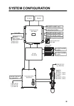
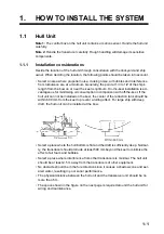


1. HOW TO INSTALL THE SYSTEM
1-10
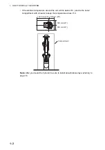
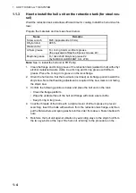
3. Peel the tape from the F mount gasket then attach the gasket to the rear of the
Control Unit.
4. Connect a ground wire (1.25sq, local supply) between the ground terminal at the
bottom of the unit and ship’s ground.
5. Set the unit to the cutout and fasten it with four self-tapping screws (M5
20) and
wave washers.
6. Set cosmetic caps to fixing holes.
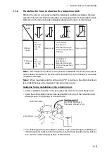
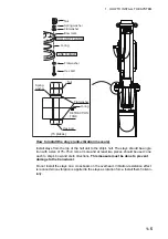
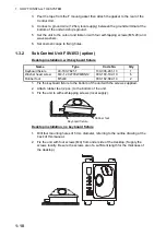
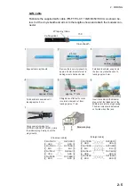
1.3.2
Sub Control Unit FSV-853 (option)
Desktop installation, with keyboard fixture
1. Fix the keyboard fixture to the bottom of the unit with the screws supplied.
2. Attach rubber feet (2 pcs.) to the bottom of the unit.
3. Fix the unit to with self-tapping screws (local supply).
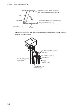
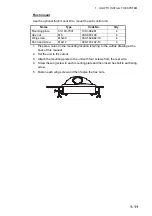
Desktop installation, no keyboard fixture
1. Drill four mounting holes of 5 mm diameter, referring to the outline drawing at the
back of this manual.
2. Fix the unit with four screws (M4) from under side of the desktop. (Supply the
screws locally. Be sure the screws are of a sufficient length for the thickness of
the desktop.)
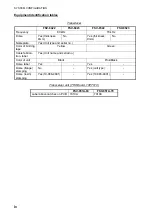
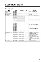
Name
Type
Code No.
Qty
Keyboard fixture
03-163-7821-1
100-306-291-10
1
Washer head screw
M4
12 C2700W MBN12
000-163-192-10
6
Rubber foot
M5x40
000-162-682-10
2
Keyboard fixture
Rubber feet
Summary of Contents for FSV-85
Page 28: ...1 HOW TO INSTALL THE SYSTEM 1 20 This page is intentionally left blank ...
Page 56: ...3 ADJUSTMENTS AND CHECKS 3 10 This page is intentionally left blank ...
Page 67: ...12 Nov 2010 Y NISHIYAMA D 1 ...
Page 68: ...4 Feb 2011 Y NISHIYAMA D 2 ...
Page 69: ...5 Nov 2010 Y NISHIYAMA D 3 ...
Page 70: ...4 Apr 2014 H MAKI D 4 ...
Page 71: ...6 Jul 2012 Y NISHIYAMA D 5 ...
Page 72: ...Nov 22 06 T Matsuguchi D 6 ...
Page 73: ...22 Apr 2013 Y NISHIYAMA D 7 ...
Page 74: ...22 Apr 2013 Y NISHIYAMA D 8 ...
Page 75: ...26 Nov 2010 Y NISHIYAMA D 9 ...
Page 76: ...27 Dec 2010 Y NISHIYAMA D 10 ...
Page 77: ...Nov 22 06T Matsuguchi D 11 ...
Page 78: ...D 12 ...
Page 79: ...29 Mar 2011 Y NISHIYAMA D 13 ...
Page 80: ...13 Sep 2011 Y NISHIYAMA D 14 ...
Page 81: ...13 Sep 2011 Y NISHIYAMA D 15 ...
Page 82: ...Mar 14 07 R Esumi D 16 ...


