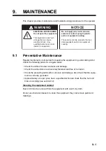
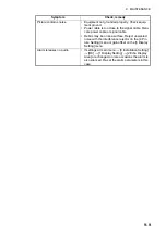
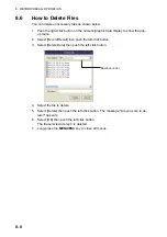
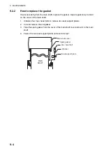
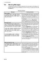
background image

9.  MAINTENANCE

9-10

9.8

Warning Messages

The table below shows the warning messages which may appear on the display. All 
warning messages are accompanied by a buzzer, which you may silence with the 

R/

B AUDIO

 key.

Warning messages

Message

Meaning, Remedy

Power supply

<<OVERVOLTAGE!! >> RETRACT TRANS-
DUCER AND TURN OFF POWER. CHECK 
SHIP’S MAINS VOLTAGE. PRESS R/B KEY TO 
TURN OFF ALARM.

This message blinks at the screen center and the 
buzzer sounds when the voltage supplied to the 
transceiver unit is excessive. Transmission is 
stopped if the equipment is transmitting, to pro-
tect the transducer and transmitter power section 
from damage. 

Silence the buzzer with the 

R/B AUDIO

 key, 

retract the transducer and turn off the power. 
Have a qualified technician check input voltage.
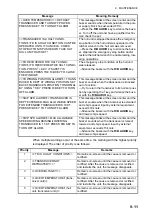
Transceiver unit

<<NO RESPONSE FROM TRANSCEIVER 
UNIT!! >> TURN OFF AND ON POWER AGAIN, 
OR CHECK POWER LINE TO TRANSCEIVER 
UNIT. PRESS R/B KEY TO TURN OFF ALARM. 

This message blinks at the screen center and the 
buzzer sounds when there is no reply from the 
transceiver unit. 

Press the 

R/B AUDIO

 key to turn off the buzz-

er. Have a qualified technician check the set. 

<<ELECTRIC CHARGE!! >>RETRACT TRANS-
DUCER AND TURN OFF POWER. CHECK 
SHIP’S MAINS VOLTAGE. PRESS R/B KEY TO 
TURN OFF ALARM. 

This message blinks at the screen center and the 
buzzer sounds if the +B voltage of capacitors in 
the transceiver unit can not be charged to prede-
termined voltage within the specified time. 

Press the 

R/B AUDIO

 key to silence the buzz-

er. Have a qualified technician check the set.

<<OVER TEMPERATURE!! >> RETRACT 
TRANSDUCER AND TURN OFF POWER. 
PRESS R/B KEY TO TURN OFF ALARM.

This message blinks at the screen center and the 
buzzer sounds when the temperature in the pow-
er supply block has exceeded 85°C;.

Press the 

R/B AUDIO

 key to silence the buzz-

er. Turn off the system and have a qualified tech-
nician check the system. 

Hull unit, transceiver unit

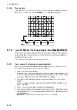
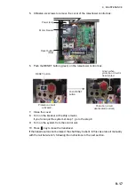
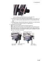
<<TRANSDUCER NOT RETRACTED!! >>CUT 
OFF POWER LINE TO MONITOR UNIT AND 
HULL UNIT. PRESS R/B KEY TO TURN OFF 
ALARM.

This message blinks at the screen center, the 
buzzer sounds and the LEDs above keys blink if 
the transducer is not raised within 15 seconds 
(800 mm stroke) or 18 seconds (1100 mm 
stroke) after pressing the 

 key. 

Press the 

R/B AUDIO

 key to silence the buzz-

er. The reason may be the transducer is tangled 
in the net or its shaft is bent or the motor bleaker 
is off. Try raising it from the hull unit as shown in 
section 9.12. 

Summary of Contents for FSV85MK2

Page 1: ...ner Road Havant Hampshire PO9 1QY U K All brand product names trademarks registered trademarks and service marks belong to their respective holders How to discard this product Discard this product according to local regulations for the disposal of industrial waste For disposal in the USA see the homepage of the Electronics Industries Alliance http www eiae org for the correct method of disposal Ho...

Page 2: ... inside the equipment Immediately turn off the power at the switchboard if water leaks into the equipment or something is dropped into the equipment Continued use of the equipment can cause fire or electrical shock Contact a FURUNO agent for service Immediately turn off the power at the switchboard if the equipment is emitting smoke or fire Continued use of the equipment can cause fire or electric...

Page 3: ...ency procedures Q If the lubricant enters eyes flush with clean water about 15 minutes Consult a physician Q If the lubricant contacts skin flush area with clean water Q If the lubricant is ingested see a physician immediately Disposal of lubricant and its container Dispose of the lubricant and its container in accord ance with local regulations If you are unclear about the disposal procedure cont...

Page 4: ...nnot be raised or lowered The transducer is also stopped when the ratchet wrench in the hull unit which is used to manually raise the transducer is re moved from its holder To release the emergency stop condition first confirm that no one is near the hull unit Then do the following To release the EMERGENCY STOP button turn the button in the direction of the arrow on the button Return the ratchet w...

Page 5: ...e full screen display 2 2 2 2 2 Horizontal2 mode 2 3 2 3 Display Range 2 4 2 4 Tilt Angle 2 5 2 4 1 How to set the tilt angle 2 5 2 4 2 Automatic tilt 2 5 2 4 3 Relation between bottom echo and tilt angle 2 7 2 4 4 Tilt angle for surface fish 2 8 2 4 5 Suitable tilt angle 2 8 2 5 How to Measure Range and Bearing to a Target 2 9 2 6 How to Eliminate Weak Echoes 2 9 2 7 How to Adjust Strong and Weak...

Page 6: ...Ship Position Mark 2 33 2 18 1 How to enter an event mark 2 33 2 18 2 How to enter an own ship position mark 2 34 2 18 3 How to erase an event mark own ship position mark 2 34 2 19 Select Mark Window 2 34 2 20 Net Course Mark 2 35 2 21 Net Behavior 2 36 2 22 Menu Items Descriptions 2 37 2 23 How to Interpret the Horizontal Display 2 40 2 23 1 Bottom and school of fish echoes 2 40 2 23 2 Unnecessar...

Page 7: ... Suppress Bottom and Sea Surface Reflections in Shallow Waters 4 11 4 10 How to Reject Sonar Interference and Noise 4 12 4 10 1 How to identify the noise source 4 12 4 10 2 Change TX interval 4 12 4 10 3 Interference rejector 4 13 4 10 4 Shift TX frequency 4 13 4 10 5 Noise limiter 4 14 4 10 6 Reverberation 4 14 4 10 7 Echo average 4 15 4 10 8 How to suppress sidelobes 4 15 4 11 How to Adjust Beam...

Page 8: ... 6 3 6 2 2 How to program the function keys 6 3 6 2 3 How to erase programs 6 4 6 2 4 How to program the function keys of sub control unit 6 5 6 3 USER PROG Control 6 6 6 3 1 How to select a user program 6 6 6 3 2 How to program the USER PROG control 6 6 6 3 3 How to program display ranges 6 7 6 4 Remote Controller option 6 8 7 OTHERS MENU 7 1 7 1 Erase Marks Menu 7 1 7 2 Wheel Setting Menu 7 2 7 ...

Page 9: ...an and Replace the Filter 9 7 9 6 Trackball Maintenance 9 7 9 7 Troubleshooting 9 8 9 8 Warning Messages 9 10 9 9 Error Codes 9 12 9 10 Status Messages 9 12 9 11 Tests 9 12 9 11 1 Test menu 9 12 9 11 2 Board test 9 14 9 11 3 Panel test 9 15 9 11 4 Test pattern 9 16 9 12 How to Raise the Transducer from the Hull Unit 9 16 9 12 1 How to raise the transducer automatically 9 16 9 12 2 How to raise the...

Page 10: ...85 MARK 2 are CE UKCA declaration With regards to CE UKCA declarations please refer to our website www furuno com for further information about RoHS conformity declarations Disclosure of Information about China RoHS With regards to China RoHS information for our products please refer to our website www furuno com Cylindrical sphere transducer provides 90 degrees vertical detection Schools of fish ...

Page 11: ...80kHz䠅 FSV 8471 MK2 FSV 8472 MK2 FSV 8481 MK2 FSV 8482 MK2 Transceiver Unit FSV 851C MK2 200 220 VAC 3I 50 60 Hz 100 110 115 220 230 VAC 1I 50 60 Hz 䠖 Use the optional Control Box Extension Box FSV 2560 to extend the distance between the raise lower control box and the hull unit Raise Lower Control Box FSV 8520 MK2 Processor Unit FSV 8503 MK2 100 230 VAC 1ø 50 60 Hz AC DC Power Supply Unit PR 241 ...

Page 12: ...SYSTEM CONFIGURATION xii This page is intentionally left blank ...

Page 13: ... stops at desired position Lowers the transducer full protrusion Adjusts the screen brilliance Note Monitor must be a compatible monitor and must be connect ed via USB to the Processor Unit Selects user programmed P1 to P10 settings Enters the net shooting mark or own ship mark H V S V1 S V2 S H V S AUTO TRAIN 1 2 3 4 5 6 7 8 9 10 11 12 13 14 15 16 17 18 19 20 21 22 24 23 26 25 28 27 Scrollwheel S...

Page 14: ...sensitivity select range set tilt and user program number Automatic transducer train width on audio bearing mark horizontal mode vertical bearing mark vertical mode Sets auto tilt angle Selects the display mode Short press Opens the menu goes back one layer in the menu Long press Closes the menu Shows the range bearing audio marker Sets the audio bearing Off centers moves the own ship symbol to th...

Page 15: ...Program Short press Confirms the selected item Long press Opens the Select Mark window Left button short press 1 Confirms your selection Used with drag drop feature 2 Inserts a fish mark factory default settings 3 Left button long press Moves the cursor to the own ship location 1 This manual abbreviates the operation of the left right buttons as follows Press the left button Left click Press the r...

Page 16: ...ter splash and spray When the remote controller is not in use return it to its designated hanging lo cation Note 2 Each key on the remote controller can be re assigned with a different function see section 6 4 No Function on control unit 1 Same as 1 F1 to 4 F4 key The program can be changed See section 6 2 4 2 Same as trackball unit on con trol unit No Function default Same function as the TILT co...

Page 17: ...e power switch until the screen goes blank If the power switch is pressed before retracting the transducer the message Raising appears and the transducer is retracted However for safety purposes make it a practice to retract the transducer before turning off the power 1 3 Raising Lowering the Transducer After the startup tests are complete only the key lamp is lit After the power is turned on all ...

Page 18: ...led in the net for some reason partially raise the transducer with the key The function of the key depends the menu setting main menu Others Mid Key Setting Fixed Position The transducer stops at the selected position If the key is oper ated while the transducer is being raised or lowered the transducer stops at the fixed position The fixed position can be set by clicking the transducer position m...

Page 19: ...ansducer protrusion The Transducer Position Mark which appears at the top left corner lets you check how far the transducer is protruding You can show or hide the marker by doing the following operation Main menu Others Initial Settings Mark Display TD Position Mark The color of the indicator changes according to transducer position and operation state Green The transducer is fully retracted Brown...

Page 20: ...ed to the processor unit via USB you can adjust the screen brilliance from the control unit Turn the BRILL knob clockwise to increase or counter clockwise to decrease the brilliance Note If your monitor is not FURUNO brilliance cannot be adjusted from the control unit Adjust the brilliance at the monitor How to adjust the panel dimmer You can change the brightness of the panel and keys with the fo...

Page 21: ...1 OPERATIONAL OVERVIEW 1 9 2 Roll the trackball to select Others then push the left button 3 Click Display Setting ...

Page 22: ... use the shortcut keys 8 F8 to adjust the panel dimmer 1 5 Display Modes There are six display modes Horizontal Horizontal1 Horizontal2 Slant single dis play Horizontal Slant Vertical1 and Vertical 1 Vertical 2 If the FSV 85 MARK 2 is fitted with dual monitors you can select how the picture data is shown on two displays Dual Display or Sub Display For details see 2nd Monitor Setting on page 7 8 Ex...

Page 23: ... Horizontal2 Vertical1 and Vertical1 Vertical2 You can program the MODE key to show any or all of the modes mentioned above For further details see Display Mode on page 7 6 The MODE key may be programmed to show a pull down menu instead of a conven tional menu 1 Push the right click button on the numeric graphic data display 2 Select Display Mode then push the left click button 3 Select the mode t...

Page 24: ...ult configuration Landscape shows two horizontal displays one up and one down Other configurations available are as shown below Desired configuration may be chosen with H2 S2 Display in the Display Setting menu For fur ther details see chapter 2 H2 mode NUMERIC GRAPHIC DATA DISPLAY NUMERIC GRAPHIC DATA DISPLAY NUMERIC GRAPHIC DATA DISPLAY N W E 2 1 1 N W E 2 1 1 85 1 H1 H2 N W S E 3 300 2 3 1 3 2 ...

Page 25: ...and one down Other configurations available are as shown below The desired configura tion can be chosen with H2 S Display in the Display Setting menu For further details see chapter 4 Bottom School of fish Sea surface reflection N W S E 3 300 2 3 1 3 2 1 N W S E 3 2 1 3 2 1 1 3 2 2 1 3 2000 2 3 1 3 2 1 1 85 1 2 Landscape display Slant mode on bottom half Portrait display Slant mode at right half S...

Page 26: ...he function assigned to each key NUMERIC GRAPHIC DATA DISPLAY NUMERIC GRAPHIC DATA DISPLAY V1 mode V1 V2 mode 㻺 㼃 㻿 㻱 㻞㻜㻜㻜 㻝㻜㻜㻜 㻝㻡㻜㻜 㻡㻜㻜 㻝㻜㻜㻜 㻝㻡㻜㻜 㻝㻜㻜㻜 㻝㻜㻜㻜 㻡㻜㻜 㻺 㼃 㻿 㻱 㻞㻜㻜㻜 㻝㻜㻜㻜 㻝㻡㻜㻜 㻡㻜㻜 㻝㻜㻜㻜 㻡㻜㻜 㼂 㻝 㻞 㻴 㻴 㼂㻝 㼂㻞 㼂㻝 㻡㻜㻜 㻡㻜㻜 㻡㻜㻜 㻝㻜㻜㻜 㻝㻜㻜㻜 㻡㻜㻜 㻡㻜㻜 142m 45m B 115 H R 400m AUTO 17 T 21 G 1 0 H UP B 330 210m 48m 148m 148m N W S E C 256 S 12 3kn 230m 70m 3 2 1 1 2 P 8 B 290 R 146m 3 2 1 1 3 2 1 2 3 2 1 ...

Page 27: ...d vertical modes are active press the H V S key to show the range and gain indications of the mode you wish to adjust Pressing the H V S key changes the color of the range and gain indications to orange H1 H2 Horizontal1 or horizontal2 V1 V2 H or V display 2 Adjust the GAIN control New gain setting is momentarily displayed in large characters at the top of each dis play The setting value is always...

Page 28: ...l button when selected with the scrollwheel If you selected TX RX Setting at step 2 for example the following menu appears 4 Press the H S V key to select the display mode H1 H2 tab Items for horizontal display setting S tab Items for the slant display setting V tab Items for the vertical display setting Items which you cannot set are shown in gray 5 Select the item then push the left click button...

Page 29: ...ental change of setting When you open one of these sub menus and select an item the confirmation message shown above right appears To change the setting of the selected item select Changeable and push the left click button to show the dialog box for the item To escape select Cancel then press the left button If you do not want to show the confirmation message above see Initialization menu on page ...

Page 30: ...1 OPERATIONAL OVERVIEW 1 18 Pop up menu operation Push the right click button on the numeric graphic data display to show the pop up menu These items can be accessed from the main menu ...

Page 31: ...programmed to Fixed Position Lowers the transducer to half protrusion If the mid protrusion key is programmed to Any Position The transducer stops at desired position Lowers the transducer to full protrusion Turn the power on Set the tilt angle Select horizontal display Press to choose the screen horizontal or vertical or horizontal1 or horizontal2 to adjust gain and range ...

Page 32: ... 㻌㻌㻔㻞㻝㻜㼙㻕 㻌㻌㻠㻤㼙 㻝㻢㻤㼙 㻡㻦㻟㻞 㻜㻚㻡㻝㻺㻹 㻝㻜 㻟㻜 㻞㻜 㻠㻜 㻡㻜 㻢㻜 㻣㻜 㻤㻜 㻝㻜㻜 㻝㻝㻜 㻝㻞㻜 㻝㻟㻜 㻝㻠㻜 㻝㻡㻜 㻝㻢㻜 㻝㻣㻜 㻝㻥㻜 㻞㻝㻜 㻞㻠㻜 㻞㻟㻜 㻞㻞㻜 㻞㻡㻜 㻞㻢㻜 㻞㻤㻜 㻞㻥㻜 㻟㻜㻜 㻟㻝㻜 㻟㻠㻜 㻟㻞㻜 㻟㻟㻜 㻟㻡㻜 㻞 㻝 㻟 㻿㻌㻾 㻠㻜㻜㼙 㻭㼁㼀㻻 㻝㻣 㼀 㻔㻞㻝 㻕 㻳 㻝㻚㻌㻜 㻴㻙㼁㻼 㻼 㻌㻌㻤 㻾㻻 㻡㻜㻿 S Trackball data Slant range Horizontal range Depth Relative bearing or True bearing Event mark data Horizontal range Present depth Depth at measured Relative bearing or True bearing Latest event...

Page 33: ...ng 4 Click H2 Display 5 Click the desired option 6 Click Quit on the setting box to close the box 7 Long press the MENU ESC key to close all menus Note Range tilt angle gain and program keys can be adjusted separately for each horizontal display Quit Display Setting Mode Selection Mode Key Echo Display Area Within Range H2 Display Landscape 2nd Monitor Setting Portrait V Scan Aspect Ratio Fixed V ...

Page 34: ...he horizontal display If the two horizontal displays are active press the H V S key to select H1 or H2 to change the range The range and gain indications of the horizontal mode must be in orange to change the range and gain 2 Operate the RANGE control to select a range Note 1 The range can also be adjusted from the range indication Put the cursor on the range indication to highlight it in yellow t...

Page 35: ...ted by rolling the scrollwheel Note 2 The tilt angle can also be adjusted from the tilt angle indication Put the cursor on the tilt angle indication to highlight it in yellow then roll the scrollwheel Note 3 The TILT control functions as a bearing setting lever when the following con ditions are met Tilt Lever in the Display Setting menu is selected to Tilt V1 and the vertical display is chosen in...

Page 36: ...arget lock function is active or is made active Auto tilt is available when the target lock is OFF Note 2 If the picture set with auto tilt is not visible disable auto tilt and try again Range m Width 1 Width2 Width3 Period 60 100 150 200 300 400 500 600 700 800 900 1000 Over 1100 4 2 1 1 1 1 1 6 4 2 2 2 2 2 8 6 4 3 3 3 3 Period One transmission Note Tilt angle changes in 2 in crements for asteris...

Page 37: ...ocated above the bottom Case 3 Tilt angle 0 to 5 This tilt angle may or may not capture the bottom since the returning bottom echo is weak The school of fish is located close to the bottom Points to consider Normally a vertically distributed school of fish is a better sonar target than the bot tom because it reflects the transmitted pulse back toward the transducer In case 3 both schools of fish a...

Page 38: ...ough they will become dominant and interfere with observation of wanted echoes To minimize these sea surface reflections and to search for schools of fish on the surface effectively the tilt angle is usually set between 4 and 5 so the upper portion of the beam becomes almost parallel with the sea surface When the sea is rough the tilt angle is slightly increased to lessen the affect of sea surface...

Page 39: ...ation and lit tle absorption If these echoes are displayed directly on the screen the size of the dis played echo from the same school of fish may change with distance making it difficult to judge the actual size of the school of fish To overcome this inconvenience use the TVG curve function This function compensates for propagation loss of sound in water amplification of echoes on short range is ...

Page 40: ...f the selected curve does not provide satis factory results try to adjust TVG Near TVG Medium or TVG Far as shown below TVG distance and setting This sonar has three TVG functions NEAR MEDIUM and FAR and they mainly compensate for propagation loss on short middle and long ranges respectively centered at the ranges shown below The higher the TVG setting the greater the amplification of echoes 1 Pre...

Page 41: ...se all menus Note When a school of fish is located on a long range setting about 800 meters and is approaching own ship do as follows 1 Adjust the tilt to keep the school of fish in the center of the sonar beam name ly the school of fish is displayed in strongest colors possible 2 Confirm that the fish echo is displayed in the same color as it approaches 3 If the color suddenly changes to weaker c...

Page 42: ...nted the unwanted and scattered echoes from close in may be excessively strong In this case a school of fish which is dis played at between 300 and 500 m may disappear gradually when the ship starts ap proaching the school of fish Use the Near AGC feature to suppress this strong echo Normally set it between 3 and 4 however this setting depends on the sea condition Do not set it too high all echoes...

Page 43: ...ck button 5 Select 2nd AGC again then push the left click button 6 Select or then push the left click button to change the setting The setting range is 0 to 20 The higher the setting the stronger the suppression on long range 7 Select Quit on the setting box then push the left click button to close the box 8 Long press the MENU ESC key to close all menus Other AGC related items on the 2ND AGC menu...

Page 44: ...ong range sounding it has the disad vantage of being poor in discrimination of targets that is the ability to separate several closely located targets When searching bottom fish therefore it is useful to shorten the pulse length in order to separate fish echoes from bottom reflections Note When searching for surface or midwater fish in which bottom reflections are not so strong use the longest pul...

Page 45: ...es clearer when the output power is reduced rather than when the GAIN is decreased as illustrated below 1 Press the MENU ESC key to show the main menu 2 Select TX RX Setting then push the left click button 3 Press the H V S key to select H1 or H2 tab 4 Select TX Power then push the left click button 5 Select or then push the left click button to change the setting The setting range is 0 9 The high...

Page 46: ... two steps has effect on the picture adjust one of the following 2 9 2 Change TX interval When other sonars nearby are oper ating the same transmission interval as that of own ship s sonar rings of interference appears on the display To remove the rings from the screen do the following 1 Press the MENU ESC key to show the main menu 2 Select TX RX Setting then push the left click button 3 Press the...

Page 47: ...e the box 7 Long press the MENU ESC key to close all menus 2 9 4 Shift TX frequency If the interference cannot be suppressed by the interference rejector or changed in TX interval shift the TX frequency from the Frequency menu 1 Press the MENU ESC key to show the main menu 2 Select TX RX Setting then push the left click button 3 Press the H V S key to select the H1 or H2 tab 4 Select Frequency the...

Page 48: ...her the setting the higher the degree of the suppression 6 Select Quit then push the left click button to close the box 7 Long press the MENU ESC key to close all menus 2 9 6 Reverberation You may select the length of reverberation for the echo signal with Reverberation on the TX RX Setting H1 or H2 tab The setting range is 0 3 The larger the value the lower the reverberation effects Set the lengt...

Page 49: ...be suppression A Watch the echoes while adjusting the suppression The setting range is 3 to 4 0 is OFF The larger the setting the more the sidelobe is suppressed For greatest sup pression use a negative setting 3 to 1 Note When a negative value is used TX RX Mode in the Display Setting menu is automatically selected to Alternative See Display Setting Menu on page 7 3 for details Sidelobe suppressi...

Page 50: ...Tilt The beamwidth is automatically widened as tilt goes deep This is convenient for keeping a watch on fish that ascend and descend TX Beam Width Increase the value to display close range echoes clearly Hor RX Beam Width Increase the value to improve horizontal resolution Ver RX Beam Width Increase the value to improve vertical resolution to distin guish fish echoes from bottom echoes RX Beam Con...

Page 51: ...s not appear on the displays where it can not be inscribed 2 11 1 How to select the target lock mode Note Target lock mode is unavailable when there is a displayed target lock mark 1 Press the MENU ESC key to show the main menu 2 Select Others then push the left click button 3 Select Initial Setting then push the left click button 4 Select Changeable then push the left click button 5 Select Target...

Page 52: ...ted position of the school of fish when the vector time elapses The tar get lock mark also appears on the vertical display however the vector is not shown If the target is lost the target lock mark changes to red color and the tracking mode changes to position mode see next section at that position When the so nar detects and tracks the target again the FISH mode is restored 4 To disable the targe...

Page 53: ...Data Selects which target lock tracking data to use horizontal or slant or both horizontal and vertical Threshold Selects the minimum signal level to use in target lock tracking The setting range is 1 to 30 Target lock tracks a target whose signal level is greater than set here Bottom Threshold When a target is judged as a bottom echo raise this setting to differentiate bottom from target The sett...

Page 54: ...m move on the screen relative to own ship s movement Course up The display is oriented according to course Own ship position is fixed at the screen center Echoes from fish and the bottom move on the screen relative to own ship s movement Targets are displayed at ship s bow True Motion Stationary objects are fixed and own ship and fish echoes move on the display in accordance with their true course...

Page 55: ... fish and bottom through the external speaker 2 13 1 How to set the bearing In the default setting the audio function is on and the audio sector is 30 1 Operate the trackball to place the cursor on the direction you want to monitor through the speaker 2 Press the R B AUDIO key The monitoring section is set on the bearing selected in a 30 60 90 180 or 330 sector centering the audio bearing mark Ech...

Page 56: ...g You may automatically scan the audio sector and audio bearing mark in the sector of 12 24 or 36 as shown below 1 First activate the range and audio bearing marks with the R B AUDIO key 2 While pressing and holding down the AUTO TRAIN key press the R B AUDIO key to select desired auto train sector among 12 24 or 36 or OFF to disable automatic training Watch the auto train mark to know the current...

Page 57: ...lect Alarm Zone then push the left click button 8 Operate the trackball to place the cursor on the starting point of the alarm zone 9 Push the left click button 10 Operate the trackball to select the ending point The display paints a fan shaped alarm zone The alarm range appears on the display as shown below 11 Push the left click button 12 Long press the MENU ESC key to close all menus When a fis...

Page 58: ... mark 2 Press the OFF CENTER key 3 To move the own ship mark back to the screen center press the OFF CENTER key again Note 1 The offcenter feature cannot be canceled in the true motion mode Switch the mode to cancel the offcenter When the OFF CENTER key is pressed the own ship mark moves to the cursor position Note 2 You can also activate the offcenter feature by Long pressing the left button with...

Page 59: ...ta and the fish histogram 3 To turn off the estimate marks press their respective keys Note The fish school mark and event mark 1 can be entered with the fish estimate mark For details contact your dealer Fish histogram The fish histogram shows in graph form signal strength distribution for the school s of fish marked with an estimate mark on the horizontal slant displays The histogram display for...

Page 60: ...rcle cursor to estimate correctly The diameter of the circle cursor is displayed below the circle cursor Note The last digit is rounded of when the diameter is greater than 100 m 4 Place the circle cursor on another school of fish to estimate the volume You can compare the volume of two schools of fish with the diameter of the school of fish 5 Right click to quit the measurement The circle cursor ...

Page 61: ...st fish mark or appears on the location selected at step 1 and any earlier fish marks are shown with an X The distance between the two fish marks and speed course and bearing of the school of fish appear at the bottom right hand corner of the hor izontal display area Note 1 The time and distance between each press of the FISH key should be as long as possible to increase accuracy of measurement Fo...

Page 62: ...the right button on the numeric graphic data display to show the pop up menu 2 Click Erase Marks 3 Click Fish Mark1 or Fish Mark2 Each click deletes the earliest fish mark 4 Long press the MENU ESC key to close all menus Note The default function of the 5 F5 key for fish mark 1 deletes the earliest fish mark Fish Mark 2 FISH key pressed once twice three times four times This data is the latest fis...

Page 63: ...rk 1 can also be entered by pushing the right button With speed and heading data the mark follows own ship s movements In the True Mo tion mode the event mark is stationary When the tilt angle is changed the present depth to event mark changes Note however that the mark s position does not change when automatic tilt is active the tilt center angle is used to position the mark Plotting an event mar...

Page 64: ...mark from the menu 1 Push the right click button on the numeric graphic data display to show the pop up menu 2 Select Erase Marks then push the left click button 3 Select Event Mark1 Event Mark2 or Own Ship Pos Mark then push the left click button Each push of the left click button deletes the oldest event mark or own ship mark 4 Long press the MENU ESC key to close all menus Note The default func...

Page 65: ...n menu 2 Click Others 3 Click the Display Setting 4 Click the Net Course Mark 5 Use the trackball to position the net course mark which is shown by a dashed cir cle 6 Push the left button to set and the dashed circle changes to a solid one 7 Long press the MENU ESC key to close all menus Note 1 To delete the net course mark select Delete at step 4 Note 2 The default function of the 0 F10 key delet...

Page 66: ...upon throwing the net into the water The following ac tions occur 2 To erase the net sonde mark and associated data press the SHOOT key again Note To turn the current mark on off see page 7 13 Net shoot mark appears at own ship position Net shoot data appears at top of the display Net sonde mark is inscribed Net depth data is displayed Net sonde data Net shoot data Net shoot mark Net depth Range E...

Page 67: ...enu Gain Offset Adjusts gain level If the GAIN control on the front panel does not provide satisfactory gain adjustment enter an offset here The setting range is 0 to 12 Signal Level Contaminated water or reflections from plankton may be painted on the screen in green or light blue These echoes may be erased in order of strength The setting range is 0 to 15 0 corresponds to the weakest color Color...

Page 68: ...the Apply button H Scan Color Curve Setting Adjusts reflected echo strength versus echo color level for currently selected color response number To adjust the curve place the trackball at the point desired then push the left click button On the horizontal axis input level relative value is shown in the range from 0 to 100 The setting range for input level is 0 100 in increments of 10 and output le...

Page 69: ...ho smoothing level in the range direction The setting range is 0 to 7 The higher the setting the greater the smoothing Smooth Echo CIR Selects echo smoothing level in the circular direction The setting range is 0 to 5 The higher the setting the greater the smoothing To set input level versus output level use the trackball to place the cursor on location desired and push the left click button ...

Page 70: ...ndition on the display the skipper can prevent net damage A Flat bottom Tilt angle 10 to 15 B Flat bottom Tilt angle 20 or more C Sloping bottom Tilt angle 20 or more Bottom Shallow bottom is displayed in a strong color and with a short tail Bottom is displayed narrower and in stronger colors when compared to A Bottom echo The bottom echo is cap tured by the entire beam The bottom echo in the fore...

Page 71: ...er bottom fish Tilt angle 30 or more Fish echo which appears before bottom can be detected Tilt angle 0 to 20 Fish echo which appears together with or after bottom can be detected Bottom Sea surface reflections School of fish Bottom echo not displayed because of decreased tilt angle Sea surface reflections are present Bottom When the tilt angle is shallow the reflection echo from bottom is weak an...

Page 72: ... by own ship or another ship can be a strong reflecting object when a decreased tilt angle is used As the wake appears as a thick continuous line it can be easily distinguished from a school of fish A wake contains many air bubbles which attenuate ultrasonic energy making it difficult to sound beyond the wake Sea surface Sea surface 10 Tilt angle indication Sea surface reflections Tilt 0 Tilt 4 5 ...

Page 73: ... or sonar on other boats as well as those on own ship For instance interference from the sonar operated on other boats will show itself on the display as in A in the figure below This interference can be suppressed by changing the TX interval with TX Interval on the H Scan Setting menu Noise from marine life shows itself on the displays as in B in the figure below This type of noise can be suppres...

Page 74: ...2 HORIZONTAL MODE 2 44 This page is intentionally left blank ...

Page 75: ...xed Position Lowers the transducer to half protrusion If the mid protrusion key is programmed to Any Position The transducer stops at desired position Lowers the transducer to full protrusion Turn the power on Select a vertical display Press appropriate key Set vertical bearing mark to display in vertical display Press to choose the screen horizontal or vertical to adjust gain and range ...

Page 76: ...S key Then the Vertical 1 display appears and the vertical bearing marker is displayed in the horizontal display with V at the tip of the marker as shown on page 3 3 If both vertical displays are activated 1 or 2 is inscribed at the tip of a vertical bearing marker Note The TILT control functions as a bearing setting lever for the vertical display1 in the conditions mentioned below The bearing of ...

Page 77: ...ring V Range R Gain G User program number P Tilt angle mark Detection aspect in vertical direction at horizontal display Range scale Target lock mark Entered on horizontal display Vertical bearing mark Cursor position reference mark Trackball data when the cursor is inside the Vertical display Slant range Horizontal range Depth Tilt angle to cursor from horizontal Vertical display 1 Trackball mark...

Page 78: ...ding relative default setting on the menu See Monitor Setting menu on page 7 8 The tilt mark is a solid and dashed line which shows in the vertical display the tilt angle set on the horizontal display The meaning of the solid and dashed lines are as shown in the table below Gain See section 1 7 Vertical bearing See subsection 3 2 2 User program See section 6 3 Display range See section 3 5 Auto tr...

Page 79: ... 36 Press and hold down the AUTO TRAIN key then press the V1 S or V2 key to select the auto train sector desired Selected sector appears in large characters for five seconds for your confirmation To cancel auto train repeat the above procedure to select OFF Note When the target lock function is active in vertical mode the following limitations apply to the auto train function V1 S mode Auto train ...

Page 80: ...om the range indication Put the cursor on the range indication to highlight it in yellow then roll the scrollwheel 3 6 How to Measure the Range Bearing to a Target Operate the trackball to place the cursor on the vertical 1 or vertical 2 display The range to the location selected is shown at the top left corner Note To show the cursor position in L L see page 7 12 Range No 1 2 3 4 5 6 Detection ra...

Page 81: ...uppressed and gradually increased as range increas es so that similar targets are displayed in the similar intensities irrespective of the ranges to them TVG curve Four TVG curves are available and they vary the gain from large to small 1 Press the MENU ESC key to show the main menu 2 Select Gain Setting then push the left click button 3 Press the H V S key to select V tab 4 Select Sel TVG Curve t...

Page 82: ...etting range 50 150 m 10 m increments Middle Setting range 300 500 m 20 m increments Far Setting range 600 1000 m 40 m increments 7 Select Quit on the setting box then push the left click button Adjust the TVG level for selected TVG distance as follows 8 Select TVG Near TVG Medium or TVG Far as appropriate then push the left click button 9 Select or as appropriate then push the left click button t...

Page 83: ...may be excessively strong In this case a school of fish which is displayed at between 300 m to 500 m and beyond may disappear gradually when the ship starts approaching the school of fish Use the Near AGC feature to suppress this strong echo Normally set it between 3 and 4 however this setting depends on the sea area Do not set it too high all echoes including noise from near distance may be paint...

Page 84: ...he suppression on long range 7 Select Quit on the setting box then push the left click button to close the box 8 Long press the MENU ESC key to close all menus Other AGC related items on the 2ND AGC menu Distance Set the start range for the 2nd AGC The setting range is 0 2000 m in 20 m increments 2nd AGC is inoperative if the display range is lower than the 2nd AGC start range Type Select the TVG ...

Page 85: ...unter occasional or intermittent noise and interference These are mostly caused by on board electronic equipment engine or propeller noise or electrical noise from other sonars being operated nearby 3 9 1 How to identify the noise source To eliminate noise effectively you should first identify the noise source as follows 1 Stop transmission on the Test menu turn on TX Turn on the power of all on b...

Page 86: ...MENU ESC key to close all menus 3 9 3 Shift TX frequency If the interference cannot be suppressed by the interference rejector or change in TX interval shift the Tx frequency with the Frequency menu 1 Press the MENU ESC key to show the main menu 2 Select TX RX Setting then push the left click button 3 Press the H V S key to select the V tab 4 Select Frequency then push the left click button 5 Sele...

Page 87: ...ns to be displayed in colors of blue to background color 1 Press the MENU ESC key to show the main menu 2 Select Display Setting then push the left click button 3 Press the H S V key to select the V tab 4 Select Noise Limiter then push the left click button 5 Select or then push the left click button to set the value setting range 0 to 15 6 Select Quit on the setting box then push the left click b...

Page 88: ...setting is increased 3 9 7 How to suppress sidelobes False echoes produced by sidelobes may appear on the display depending on the dis tribution pattern of a school of fish and the positional relationship between it and a ma rine object reef etc and wake reverberation To reduce these sidelobes use Sidelobe Sup on the TX RX Setting menu on the V tab Watch the echoes while adjusting the suppression ...

Page 89: ...th is automatically controlled with the range setting TX Beam Width Increase the value to display close range echoes clearly Hor RX Beam Width Increase the value to improve horizontal resolution Ver RX Beam Width Increase the value to improve vertical resolution to distin guish fish echoes from bottom echoes RX Beam Control Increase the value to improve horizontal resolution Note When RX Beam Cont...

Page 90: ...g to Wide to double the range of the control Display Setting menu Gain Offset Adjusts gain level If the GAIN control on the front panel does not provide satisfactory gain adjustment enter an offset here The setting range is 0 12 Signal Level Contaminated water or reflections from plankton may be painted on the screen in green or light blue These echoes may be erased in order of strength The settin...

Page 91: ...onsidering their high speed and penchant for leaping and diving However the vertical display with its wide range in the vertical direction makes this task easier 3 12 1 Searching Neither the naked eye nor binoculars can continually track schools of fish which make lightning quick runs between the surface and midwater A sonar however provides a continuous view of several hundred meters of sea area ...

Page 92: ...flock of birds hovering over the sea surface is usually a good indication of the presence of a school of fish the sonar can better verify the size of a school of fish 3 12 4 Catching While the sonar operator monitors the sonar for other schools of fish the crew can scatter bait and water to attract fish to the boat School of fish School of fish School of fish School of fish ...

Page 93: ...sition Lowers the transducer to half protrusion If the mid protrusion key is programmed to Any Position The transducer stops at desired position Lowers the transducer to full protrusion Turn the power on Select single S mode or combination S mode Select mode horizontal vertical H1 H2 for range and gain adjustment Adjust the tilt Push applicable key For setting train angle V1 Left V2 Right ...

Page 94: ...e mark data North mark Range mark and audio bearing mark data Scan data Range Tilt Current auto tilt Train angle Gain User program no Fish track Fish movement vector Auto train mark Line connecting fish marks Wind speed direction Audio bearing mark Requires appropriate sensor Shown with head up mode The Slant mode presents a half circle picture The data display is mostly the same as the horizontal...

Page 95: ...with the drag and drop operation To select desired combination display do the following 1 Press the MENU ESC key to show the main menu 2 Select Others then push the left click button 3 Select Display Setting then push the left click button 4 Select H2 S Display then push the left click button 5 Select the item desired then push the left click button 6 Select Quit on the setting box then push the l...

Page 96: ... is emitted When the sound wave is emitted horizontally the tilt angle is said to be 0 and when vertically 90 The tilt angle can be set between 5 upward to 90 downward in increments of 1 4 4 1 How to set the tilt angle To manually set a tilt angle operate the TILT control Watch the tilt angle indication and tilt angle indicator is momentarily displayed in large characters at the top of the screen ...

Page 97: ...d AUTO TILT key are set to 800 m 8 and width 1 respectively the tilt angle changes at each transmission as follows 8 9 8 7 8 Note 1 The AUTO TILT key is inoperative when the target lock function is active or is made active Auto tilt is resumed once target lock is disabled Note 2 If the picture set with auto tilt is not visible disable auto tilt and try again Range m Width 1 Width2 Width3 Period 60...

Page 98: ...k mark is entered When target lock is disabled auto train resumes from the bearing in use at the time of deactivation of target lock Note When using the auto train function in slant mode the train angle size is smaller than normal 4 6 How to Measure Range and Bearing to a Target Operate the trackball to place the cursor on the target you want to measure the range and bearing The range bearing and ...

Page 99: ... gradually increased as range increas es so that similar targets are displayed in the similar intensities irrespective of the ranges to them TVG curve Four TVG curves are available and they vary the gain from large to small 1 Press the MENU ESC key to open the main menu 2 Select Gain Setting then push the left click button 3 Press the H V S key to select the S tab 4 Select Sel TVG Curve then push ...

Page 100: ...ak echoes remain unaf fected a small school of fish becomes easier to detect Adjust it so that the AGC works only on bottom reflections Do not set it too high weak echoes may be missed 1 Press the MENU ESC key to show the main menu 2 Select Gain Setting then push the left click button 3 Press the H V S key to select the S tab 4 Select AGC then push the left click button 5 Select or then push the l...

Page 101: ...ick button to change the setting The setting range is 20 to 20 The higher the setting the stronger the echo level on near range 7 Select Quit on the setting box then push the left click button to close the box 8 Long press the MENU ESC key to close all menus Note The effective range is set at Near AGC Distance on the Near AGC menu 20 m to 2000 m 20 m step 4 8 3 2nd AGC While it is ideal to suppres...

Page 102: ...AGC The larger the figure the greater the suppression Post2nd AGC Distance Switch between Far and Near Post 2nd AGC The Post 2nd AGC functions independently of 2nd AGC If the 2nd AGC cannot suppress the bottom echo or sea surface reflections try to suppress them with the Post 2nd AGC For particularly strong echoes raise the AGC setting 4 8 4 How to shorten pulse length The pulse length determines ...

Page 103: ...with wanted fish echoes and they can not be eliminated sufficiently with the aforemen tioned TVG and AGC functions especially when the TILT is set to a larger angle in order to track schools of fish approaching within 400 m In such cases try to reduce the output power by adjusting the Tx output instead of turning down the gain The pic ture becomes clearer when output power is reduced rather than w...

Page 104: ... transmission interval as that of own ship s sonar rings of inter ference appears on the display To remove the rings from the screen do the following 1 Press the MENU ESC key to show the main menu 2 Select TX RX Setting then push the left click button 3 Press the H V S key to select the S tab 4 Select TX Interval then push the left click button 5 Select or then push the left click button to change...

Page 105: ...n to close the box 7 Long press the MENU ESC key to close all menus 4 10 4 Shift TX frequency If the interference can not be suppressed by the interference rejector or change in TX interval shift the Tx frequency with the Frequency menu 1 Press the MENU ESC key to show the main menu 2 Select TX RX Setting then push the left click button 3 Press the H V S key to select the S tab 4 Select Frequency ...

Page 106: ...setting causes unwanted reflections to be displayed in colors of blue to background color 1 Press the MENU ESC key to show the main menu 2 Select Display Setting then push the left click button 3 Press the H V S key to select the S tab 4 Select Noise Limiter then push the left click button 5 Select or then push the left click button to adjust the setting The setting range is 0 to 15 6 Select Quit ...

Page 107: ...ip between it and a ma rine object reef etc and wake reverberation To reduce these sidelobes use Sidelobe Sup on the TX RX Setting menu S tab For normal suppression use Sidelobe Sup A The setting range is 3 to 4 and 0 is the default setting The higher the value the greater the suppression A minus value 3 to 1 provides increased suppression 4 11 How to Adjust Beam Width The width of the horizontal ...

Page 108: ...matically selected to Alternative See Display Set ting Menu on page 7 3 Available only when Beam Control is set to Manual 6 Select Quit on the setting box then push the left click button to close the box 7 Long press the MENU ESC key to close all menus 4 12 How to Track a School of Fish The target lock function automatically tracks a school of fish so you will not lose sight of it on the display T...

Page 109: ...et lock mark red is put on the fish school echo The target lock mark changes to white with vector when the school of fish is locked The vector shows the speed and direction of movement of the school of fish The tip of the vector is the estimated position of the school of fish when the vector time elapses The tar get lock mark also appears on the vertical display however the vector is not shown If ...

Page 110: ... data display Estimate Mark enables the esti mate mark 1 2 histogram Est Fish Info enables the both the estimate mark 1 2 histogram and data display Tracking Data During the slant mode H S display is adopted for all functions Threshold Selects the minimum signal level to use in target lock tracking The setting range is 1 to 30 Target lock tracks a target whose signal level is greater than set here...

Page 111: ...ears on the bearing selected in a 30 60 90 180 or 330 sector centering the audio bearing mark Echoes are monitored through the speaker Note To erase the range mark and the data at the bottom of the screen put the cursor near own ship mark and press the R B AUDIO key Note that the audio bearing is erased when Audio on the Alarm Audio menu is turned off 4 13 2 How to select the audio sector Select t...

Page 112: ... the audio signal The setting range is 0 9 and the default set ting is 0 4 14 Fish Alarm The fish alarm sounds the buzzer when a fish echo above a preset strength enters the operator set alarm zone 1 Press the MENU ESC key to show the main menu 2 Select Others then push the left click button 3 Select Alarm Audio then push the left click button 4 Select Fish Alarm then push the left click button 5 ...

Page 113: ... ending points Note 2 The echo strength which triggers the alarm can be set with ALARM LEVEL on the Alarm Audio menu The setting range is 0 30 This value corresponds with the 32 echo colors To disable the alarm select OFF in the procedure on the previous page 4 15 How to Relocate a School of Fish The offcenter features functions to relocate a school of fish 4 15 1 Manual offcenter 1 Operate the tr...

Page 114: ...0 45 60 set on menu Automatic offcentering is available regardless whether the train angle setting value is the same or larger than actual train angle 1 Open the Others menu from the main menu 2 Select Display Setting then push the left click button 3 Select S Auto Off Cent then push the left click button This function is only oper ative when the slant combination display is active in horizontal s...

Page 115: ...ta display 2 Operate the trackball to place the cursor on a school of fish and then press the ESTIMATE 2 key Compare estimate figures for each school of fish by observing estimate mark data and the fish histogram 3 To turn off the estimate marks press their respective keys Note The fish school mark and event mark 1 can be entered with the fish estimate mark For details contact your dealer 4 16 2 H...

Page 116: ...e You can compare the volume of two schools of fish with the diameter of the school of fish 5 Push the right click to quit the measurement The circle cursor is changed to the normal cursor Note 1 Select the event mark 1 event mark 2 fish mark target lock mark estimate mark 1 or estimate mark 2 from the Select Mark window Push the left click to enter the mark Note 2 Set the diameter of the circle c...

Page 117: ... mark or appears on the target the 2nd latest fish mark or appears on the location selected at step 1 and any earlier fish marks are shown with an X The distance between the two fish marks and speed course and bearing of the school of fish appear at the bottom right hand corner of the slant mode display area Note 1 The time and distance between each press of the FISH key should be as long as possi...

Page 118: ...ce the cursor on the fish mark you want to erase The color of the fish mark changes from white to red when the fish mark is correctly selected Press the DELETE MARK key to delete the fish mark 1 Push the right click button on the numeric graphic data display to show the pop up menu 2 Click Erase Marks 䊻 䊻 䊻 䊻 䊻 䊻 Fish Mark 2 FISH key pressed once twice three times four times This data is the lates...

Page 119: ...ce an event mark 2 Press the EVENT key The horizontal range depth and bearing to the event mark appear at the bottom left corner of the slant mode display area The event mark 1 can be entered by pushing the right click button With speed and heading data the mark follows own ship movements In the True Mo tion mode the event mark is stationary When the tilt angle is changed mark position changes wit...

Page 120: ... push the left click button Push the left click button again to delete the earliest mark 4 Long press the MENU ESC key to close all menus Note The default function of the 3 F3 for event mark 1 and 4 F4 for event mark 2 keys delete the oldest event mark or own ship mark 4 19 Net Course Mark Before shooting the net decide the shoot timing considering tide direction distance to the school of fish and...

Page 121: ...ve net data after the throwing of the net Press the SHOOT key just upon throwing the net into the water to display the net shoot data and net depth data To erase the data press the key again Note To enable this feature set Event Key to Event in the Mark Display menu Set net course mark Move trackball cursor to net course mark position and left click Press R B key to cancel Net course mark NET SHOO...

Page 122: ...ting to Wide to double the range of the control Display Setting menu Gain Offset Adjusts gain level If the GAIN control on the front panel does not provide satisfactory gain adjustment enter an offset here The setting range is 24 to 12 Signal Level Contaminated water or reflections from plankton may be painted on the screen in green or light blue These echoes may be erased in order of strength The...

Page 123: ... echo color level for currently selected color response number Picture Setting menu Smooth Echo RNG Selects echo smoothing level in the range direction The setting range is 0 7 The higher the setting the greater the smoothing Smooth Echo CIR Selects echo smoothing level in the circular direction The setting range is 0 5 The higher the setting the greater the smoothing ...

Page 124: ...on the screen as a thick line which realistically shows the bottom contour When the tilt angle is decreased the bottom trace becomes wider and weaker By observing bot tom condition on the screen you may prevent the net from being damaged by a reef or a shipwreck Bottom Bottom Bottom This distance shows depth of water Sea surface reflections Sea surface reflections Bottom Ridge Bottom Bottom Sea su...

Page 125: ... From the left figure the operator can know the horizontal distribution of the school of fish and from the right figure the vertical distribution School of fish on surface School of fish on bottom Width Horizontal distribution Thickness vertical distrtribution Depth Distance Tilt 20 degrees Sector Center 0 degrees Range 400 m Tilt 90 degrees Sector Center 300 degrees Range 400 m Bottom Sea surface...

Page 126: ...extended area as illustrated below Wake A wake produced by own ship or another ship can be a strong reflecting object when a narrow tilt angle is used As the wake appears as a thick continuous line it can be easily distinguished from a school of fish A wake contains many air bubbles which at tenuate ultrasonic energy making it difficult to sound beyond the wake Sea surface reflections Wake produce...

Page 127: ...ky and hard strong signals are detected by the sidelobe These are rep resented on the display as a false echo as shown below Noise and interference Interference from a sonar on another ship appears on the screen as shown in A B shows Interference from electrical equipment on board own ship Noise from marine life appears on the display as shown in C Bottom Bottom False echo Main lobe Bottom Sea sur...

Page 128: ...4 SLANT MODE 4 36 This page is intentionally left blank ...

Page 129: ...10 35 C WATER TEMP 8 12 10 0 10 20MIN Heading Course Speed Navigator type in brackets DGPS Differrential GPS KGPS Kinematic GPS FGPS Floating GPS GPS GPS LC Loran C DR Dead Reckoniong Position error Water current speed and direction for three layers Net sonde depth data Fish histogram See page 2 31 Water temperature Water temperature graph Position format 32 52 150N 132 12 150E Depth Requires appr...

Page 130: ...atitude and lon gitude If posi tion data is lost the last entered position is shown in red Lat 90 00 000S 90 00 000N Lon 179 59 999W 179 59 999E 180 00 00 0 00 000 Lat Lon Position sen sor The position sensor type is displayed in brackets When the posi tion sensor is not connected the brackets are left blank DGPS KGPS FGPS GPS LC DR Note is dis played when the posi tioning error occurs GPS Loran C...

Page 131: ...Vertical axis C F Horizontal axis Time 20 min 1h 6h 12h 24h Vertical axis Temp 4 C 8 F fixed width auto shift C F Data Display menu Info on school of fish Shows informa tion about school of fish during target lock operation Length Distance to school of fish in range direction Width Distance to school of fish in bearing direction Height Vertical distance Dimensions Horizontal dimension of school of...

Page 132: ...5 NUMERIC GRAPHIC DATA DISPLAY 5 4 This page is intentionally left blank ...

Page 133: ...etting menu to the user menu Some menu items cannot be programmed to the user menu See the menu tree on page AP 1 to AP 5 for items which can be programmed 1 Push the right click button on the numeric graphic data display to show the pop up menu 2 Select Wheel Setting then push the left click button 3 Select S Mode then push the left click button more than one second The mes sage User Menu Registr...

Page 134: ...econds The message Delete Registration Selected item will be removed from main menu Are you sure appears 4 Select Remove then push the left click button to delete 5 Long press the MENU ESC key to close all menus 6 2 Function Keys 1 F1 0 F10 The function keys provide one touch display of desired menu item or entire menu The default function key settings are as below Not all menu items and menus may...

Page 135: ...on key or register a timer function to a function key as shown below Note that some menu items cannot be programmed to the function keys See the menu tree on page AP 1 to AP 5 for items which can be programmed for function keys 1 Press the MENU ESC key to open the menu 2 Place the cursor on the desired function and select to highlight it in yellow To reg ister the timer function left click on the ...

Page 136: ...ton 3 Select Register then push the left click button 4 Select Clear F KEY Setting then push the left click button 5 Select Changeable then push the left click button 6 Select the function key for which you want to erase its program then push the left click button Repeat this step for other function keys 7 Select Quit on the setting box then push the left click button 8 Long press the MENU ESC key...

Page 137: ...s 1 Press the 8 F8 9 F9 and 10 F10 keys in order while pressing the MENU ESC key to activate the program registration mode on the sub control unit 2 Press the MENU ESC key to close the menu 3 Press and hold down the applicable key of the control unit and then press a func tion key of the sub control unit When the registration is completed the buzzer sounds 4 Operate the function key programmed to ...

Page 138: ...tings at the next power on Note The user program no can also be adjusted from the user program no indica tion Put the cursor on the user program no indication to highlight it in yellow then roll the scrollwheel 6 3 2 How to program the USER PROG control 1 Set the display appropriately When a combination mode is shown press H V S key to select the display to pro gram 2 Press the MENU ESC key to sho...

Page 139: ...rams for slant mode Slant combination display Horizontal display user programs when horizontal display is active Slant display user programs when slant display is active 6 3 3 How to program display ranges To use programmed ranges turn on Auto User Prog Sel For example you set P3 for 200 P7 for 1000 m etc Then the short and long ranges are selected alternately without operating the USER PROG contr...

Page 140: ...ister then push the left click button 4 Select Remote key Setting then push the left click button Note Ch7 through Ch10 are only used when an external switch is connected to the TB1 port of the Processor Unit 5 Select the item Ch1 to Ch6 corresponding to the key whose setting you want to change 6 Left click the function to register 7 Left click Quit in the setting box 8 Close the menu RANGE GAIN T...

Page 141: ...or track you want to delete then push the left click button The earliest mark is deleted For ship s track approximately 10 of the track is erased with each push of the left click button 3 To continue erasing marks push the left click button 4 Long press the MENU ESC key to close all menus Note The default function of the 3 F3 for event mark 1 4 F4 for event mark 2 5 F5 fish mark 1 and 6 F6 for own...

Page 142: ... on the Other menu then push the left click button This menu can be also opened from the pop up menu 2 Select H Mode S Mode V Mode or Wheel then push the left click button 3 Select the function to assign to the scrollwheel then push the left click button 4 Select Quit on the setting box then push the left click button to close the box 5 Long press the MENU ESC key to close all menus H Mode S Mode ...

Page 143: ...p menu is set between 3 and 1 Sidelobe Sup B on the Sidelobe Sup menu is set to a value other than 0 and RX Beam Control on the Beam Width menu is set to a value other than 0 TX RX Mode Determines how display modes are chosen MODE key or pull down menu Echo Disp Area Selects the echo display mode for the horizontal and slant displays Within Range or Full Screen H2 S Display Selects the combination...

Page 144: ...lay Auto Tilt Selects the auto tilt angle Wide 2 to 10 4 to 16 6 to 20 or Narrow 1 to 4 2 to 6 3 to 8 Net Course Mark Inscribes deletes the net course mark For further details see section 2 20 Key Beep Volume Sets the volume of the beep which sounds for key operation The setting range is 0 7 0 turns off the key beep Dimmer Change the brightness of the panel and keys The setting range is 0 15 Timer...

Page 145: ...o menus Fish Alarm Turns the fish alarm function on or off The default setting is off Alarm Level Sets the minimum echo color which triggers the fish alarm The setting range is 0 30 Alarm Zone Sets fish alarm zone Ship SPD Alarm The default setting is ON The alarm is released if ship s speed ex ceeds the following limits Lowering transducer 18 knots Raising transducer 15 knots Audio Turns the audi...

Page 146: ...tion key Clear F KEY Setting Erases program assigned to a function key H Scan Range Presets the horizontal mode ranges as selected with the RANGE control The setting range is 60 2000 m S Scan Range Presets the slant mode ranges as selected with the RANGE control The setting range is the same as that for H Scan Range V Scan Range Presets the vertical scan ranges as selected with the RANGE control T...

Page 147: ...NU ESC key to show the main menu 2 Select Others then push the left click button 3 Select Initial Setting then push the left click button 4 Select Changeable then push the left click button For Target Lock and Test see page 2 21 and page 9 12 respectively Note Alpha blending technology is used for transparency effects For service technician ...

Page 148: ...again after you change this setting OFF Select if a single monitor is connected Dual Display Main and sub monitors show different pictures in the combination dis play mode Sub Display Main and sub monitors show the same picture in the combination dis play mode Monitor Resolution Monitor Resolution options are SXGA UXGA and WUXGA To reflect the setting change turn on off the power After changing th...

Page 149: ...ng menu then push the left click button Heading Mark The heading mark is a dashed line which indicates the heading in all presentation modes It extends from own ship position to the outer edge of the display and appears at zero degrees in the head up mode It changes the orientation depending on ship s orientation in the north up course up and true motion modes Range Rings The range rings are the d...

Page 150: ...et Vector This is a line extending from the target lock mark and it shows speed and direction of tracked school of fish See the illustration below for appear ance Fish Track Plot Traces target movement in target lock Requires speed and course data EVENT Key Selects the key to enter the own ship s position mark Event key Shoot key Histogram Disp Shows signal strength distribution for the school s o...

Page 151: ...r small size Own Ship Pos Mark Shows the own ship position mark in normal large or small size Own Ship Mark Selects size of own ship mark to standard large or actual Net Shoot Mark You may show the net shoot mark in normal large or small size Estimate On Scan Selects the size of the fish estimate mark on the horizontal display for large or small Current Vector The length of the current vector may ...

Page 152: ...ects how to display course 32 CMPS 32 compass points 360 True true bearing 360 360 Relative 180 180 Relative 180 shows xxxS in case of starboard direction xxxP in case of port direction xxx 1 to 180 Heading sen sor is required to set to 360 True 32 CMPS shows bearing with alphabet indication for example N N E NNE NE1 N etc Only 180 is available for the turn an gle of the slant display Current Data...

Page 153: ...wn ship mark On Ship Pos Mark Shows or hides the current mark on the own ship position mark On Net Shoot Mark Shows or hides the current mark on the net shoot mark Current Flow Dir Selects how to display current data FROM shows from what di rection the current is flowing TO shows the direction the current is heading Requires connection of a current indicator Wind Selects wind display OFF relative ...

Page 154: ...n push the left click button to set the distances Net Length Sets net length in increments of 100 m Setting range is 1200 m to 3000 m The minimum setting range for net length varies depending on the settings for Number of XMTR and XMTR Distance Depth Display Selects which sonde depth data to show Select this item and push the left click button to select net sondes The check mark shows current sele...

Page 155: ...t at each layer Determine degree of difference among layers considering net sea condi tions etc If 50 is set for example the net movement plot mark moves at speed of 50 of water current speed 7 6 9 Stabilization menu The Stabilization menu compensates for the affects of pitching and rolling Select Stabilization on Initial Setting menu then push the left click button Requires a iner tial measuremen...

Page 156: ...lt settings After ap plying the settings restart the equipment Note 2 The transducer position setting is also set to default and the message UNREGISTERED appears See the Installation Manual IME 13670 for how to en ter transducer position Item Attribution Locks unlocks protected menu settings Asterisk marked items on this page and Ship Speed in the Alarm Audio menu cannot be adjusted by the user Da...

Page 157: ...2 Select Record Recall then push the left click button 3 Select Destination To Save then push the left click button 4 Select Reference on the Destination To Save window then push the left click but ton Note Disk capacity of the D drive is subject to change 5 Specify the location where to save the still image from the pull down menu D drive saves a still image to a folder whose name is automaticall...

Page 158: ...Image 4 To enter a comment check the box for Insert Comments 5 Click the button on the Still Image window to save the still image The picture at the moment the button is pushed is shown on the display preview If you checked the box for Insert Comments the software keyboard appears If you did not check the box for Insert Comments the preview disappears after four seconds 6 Click the character or sy...

Page 159: ...l to enter the comment max 20 characters or sym bols 5 Click Enter to close the software keyboard and the still image preview Note 1 The default function of the 1 F1 key saves the still image Note 2 You can select how long to show the preview display Contact your dealer for details Dual display Select the monitor on which to capture the still image 1 main monitor 2 sub monitor 1 Right click the nu...

Page 160: ...ll image is shown on the display Note The window can be resized and moved by drag and drop Also you can zoom in out with the scrollwheel Resize the window if the still image is not fully displayed 4 Select Quit on the still image window then push the left click button to close the window Note The default function of the 2 F2 key displays the recalled still image window How to display a still image...

Page 161: ...p menu 2 Select Record Recall then push the left click button 3 Select Setting File then push the left click button 4 Select Save then push the left click button The file is given a name FSV85_yyyy_mm_dd_hh_mm_ss ini then shown in the box 5 Select a destination to save from the pull down list 6 Select Save then push the left click button The progress bar at the bottom of the box shows the saving p...

Page 162: ...e pop up menu 2 Select Record Recall then push the left click button 3 Select Setting File then push the left click button 4 Select Load then push the left click button 5 Select the file to load 6 Select Load then push the left click button The progress bar at the bottom of the box shows the loading progress The Set ting File menu is appears when the saving is completed 7 Long press the MENU ESC k...

Page 163: ... User Prog then push the left click button 5 Select a file to load from the destination list 6 Select the setting number from the User Program to load list then push the left click button 7 Select the setting number to load from the User Program to set list then push the left click button 8 Select Load then push the left click button The progress bar at the bottom of the box shows the loading prog...

Page 164: ... up menu 2 Select Record Recall then push the left click button 3 Select Delete Data then push the left click button 4 Select the file to delete 5 Select Delete then push the left click button The massage Are you sure to de lete appears 6 Select OK then push the left click button The file selected at step 4 is deleted 7 Long press the MENU ESC key to close all menus Destination list ...

Page 165: ...grounded Approximately once per year have a qualified technician check that the hull unit brake is working see section 9 2 Cleaning the equipment cabinet Dust or dirt can be removed from the equipment with a soft dry cloth Do not use chemical cleaners to clean the equipment they can remove paint and markings WARNING NOTICE Do not apply paint anti corrosive sealant or contact spray to plastic parts...

Page 166: ... main shaft with Daphne Grease MP No 2 IDEMITSU KOSAN CO LTD 1 every six months Coat gear shaft with Daphne Grease MP No 2 IDEMITSU KOSAN CO LTD 1 every six months Dry dock ship and clean transducer face yearly Apply single coat of SEATENDER 20 2 anti foulant to transducer face to keep marine life off the transducer Do not paint metallic parts such as the transducer flange 1 Equivalent greases SHO...

Page 167: ...anually with the ratchet wrench see section 9 12 2 apply Molytone No 2 grease How to grease the gear shaft Inject Daphne Grease MP No 2 IDEMITSU KOSAN CO LTD to the grease nipple to grease the gear shaft Gear cover window Wing nuts Operation image Operation image Inject grease until a slight amount comes out here Inject grease until a slight amount comes out here Grease nipple Grease nipple ...

Page 168: ...ver of the main shaft 1 Unfasten four hex head bolts to remove two seal support plates 2 Cut and remove the old gasket 3 Take the spare gasket from the cover of the main shaft cover and set it to the main shaft 4 Fasten the two seal support plates removed at step 1 Hex head bolt Washer Seal support plate Main shaft cover MAIN SHAFT Spare gasket ...

Page 169: ...ad bolts Tighten the hex head bolts 4 Coat the holes for the hex head bolts with silicone sealant CAUTION CAUTION Replace the anti corrosion zinc plates yearly Corrosion may result allowing water leakage and or loss of transducer The clearance between the hull and the ground or deck must be 650 mm or more Anti corrosion zinc plate Hex head bolt Spring washer Flat washer Part Name Zinc plate Type Z...

Page 170: ... in the processor unit Check the circuit breaker in the transceiver unit The breaker is behind the lid at the front right bottom corner of the unit Find the cause before replacing a fuse If the fuse blows again after replacement con tact your dealer for advice These fuses are located inside the equipment and may contain high voltage Under no circumstances should these fuses be replaced by the user...

Page 171: ...trackball housing in cluding the lens as shown below 1 Turn the retaining ring on the trackball module in the direction of the arrows see figure below to unlock it then remove the retaining ring 2 Use cellophane tape to remove the trackball from the trackball housing Place the trackball and the retaining ring on a clean soft cloth laid on a flat sur face 3 Clean the ball with a damp soft cloth the...

Page 172: ...and pro cessor unit Press and hold the power key for approximately seven seconds to force shut down the equipment Cannot operate the equipment Check connections between control unit and pro cessor unit Strange noise from hull unit Gears may require re greasing See section 9 2 Bottom echo becomes irregular Rough seas Distance to the bottom changes due to rolling and pitching Long range selected Tra...

Page 173: ...is may be on sea surface Reject unwanted noise with the interference rejector on the 4 Pic ture Setting menu or gain offset on the 3 Display Setting menu Alarm releases no audio If settings at main menu 9 Installation Setting OK 1 Display Setting 2 Echo Display Area are changed on rare occasions the alarm is also silenced Re set the alarm parameters in this case Symptom Check remedy ...

Page 174: ...nician check the set ELECTRIC CHARGE RETRACT TRANS DUCER AND TURN OFF POWER CHECK SHIP S MAINS VOLTAGE PRESS R B KEY TO TURN OFF ALARM This message blinks at the screen center and the buzzer sounds if the B voltage of capacitors in the transceiver unit can not be charged to prede termined voltage within the specified time Press the R B AUDIO key to silence the buzz er Have a qualified technician c...

Page 175: ...enter and the buzzer sounds when the transducer is knocked out of position Try to return the transducer to its normal posi tion by operating the key and silence the buzz er with the R B AUDIO key SHIP SPD ALARM TRANSDUCER IS KEPT EXTENDED MAX ALLOWABLE SPEED FOR EXTENDED TRANSDUCER IS 18 KT PRESS R B KEY TO TURN OFF ALARM This message blinks at the screen center and the buzzer sounds when the tran...

Page 176: ... the test results for any test contact your dealer 9 11 1 Test menu 1 Press the MENU ESC key to show the main menu 2 Select Others then push the left click button 3 Select Initial Setting then push the left click button 4 Select Changeable then push the left click button 6 ELECTRIC CHARGE Remains on screen until the cause is removed or rectified After the cause is removed or rectified and restarts...

Page 177: ...9 MAINTENANCE 9 13 5 Select Test then push the left click button Note The menu item TX turns transmission on off Turn off transmission to specify the source of noise for example For technician ...

Page 178: ... starter program boot pro gram application program BOARD TEST TRCPU 0 BMF 0 105 0790 XX XX 105 0791 XX XX ROM OK RAM OK TDS OK DATA OK RDS1 OK RDS2 OK FDS1 OK FDS2 OK INC TRX TEST OK PITCH 12 3 ROLL 2 5 PW R 12V 12 2V B 120 5V 0 0 0 0 0 F 0 0 0 0 0 0 0 0 0 0 105 XXXX XX XX 105 XXXX XX XX 105 XXXX XX XX ROM OK RAM OK 105 XXXX XX XX 105 XXXX XX XX 105 XXXX XX XX ROM OK RAM OK TD TEMP 76 4C S2 000000...

Page 179: ...ockwise rotation Negative value No rotation 0 Lever check Press the lever upward or downward Normal conditions are 1 for up ward and 2 for downward Trackball check Operate the trackball X Y coordinates of trackball position are dis played Normal conditions are as follows Rightward X positive Leftward X negative Upward Y positive Downward Y negative 䠆 䠆 PAN EL TEST X 0 Y 0 d 0 0 0 0 0 0 0 0 0 0 0 0...

Page 180: ... unit do as follows 1 Check the LEDs on the hull unit When the L SW_LED on the raise lower control box flashes the raise lower func tion may be abnormal Do the following steps to raise the transducer then contact your dealer When you can not check the LEDs go to step 2 2 Turn off the switchboard transceiver unit and hull unit from the ship s mains breaker To force a system shut down press and hold...

Page 181: ...tep 1 go to the step 8 9 Turn on the system from the control unit 10 Press key to raise the transducer If the transducer cannot be raised the shaft may be bent In this case raise it manually with the ratchet wrench following the instructions in the next section Motor breaker Reset button blue Power lamp RESET button Protection circuit activated Push RESET button Protection circuit deactivated norm...

Page 182: ...Note Hold the ratchet wrench when releasing the brake to prevent the transduc er from falling 5 Turn the ratchet wrench counter clockwise to raise the transducer 6 After retracting the transducer into the tank set the release lever to the holder 7 Remove the ratchet wrench and return it to its holder Restore the motor brake to its normal position Note Be sure to return the ratchet wrench to its ho...

Page 183: ...LEDs on the circuit board does not change If the main shaft lowers or the LED lighting pattern changes release the brake release push switch The drive shaft brake is abnormal check the drive shaft brake 5 Set the toggle switch to the ABRAKE side 6 Check that the Brake LED on the circuit board is lit The LED does not light when the drive shaft gear brake control circuit is abnormal If the LED is OF...

Page 184: ...to release the two C clips one to either side of the brake 2 Pull the brake release lever to unlock the brake 3 Remove the brake release level with a set of pliers 4 Remove the brake release lever pin with a pair of pliers C clip locations C clips Brake release lever Lock 䝤䝺䞊䜻䜖䜛䜑䝢䞁 䝤䝺䞊䜻䜖䜛䜑䝢䞁 ...

Page 185: ...e fan 7 Unfasten both release plates one on either side with a hex wrench then remove the plates 8 Referring to the following figure unfasten the three screws then remove the wa terproofing cover and washer Bolt Bolt Remove brake cover Remove brake cover Fan bolt Fan bolt Release plate Release plate Screws ...

Page 186: ...gap If you can insert the 0 6 mm leaf do steps 1 to 3 below 1 Loosen three hex bolts to remove spacer gap adjustment shim bolt assem bly and fixing plate Note Be careful not to drop the gap adjustment shim Gap gauge Leaf Loosen two wing screws to slide the cover and remove the gap gauge Measure gap here Moving core Fixed core Fixing plate Spacer Gap adjustment shim Bolt assy Hex bolts Hex bolts Fi...

Page 187: ...e holes on the waterproofing washer and the release plate fixing holes If the locking pins do not fit easily the holes may be mis aligned Check the alignment and re align as necessary There is a chance to drop the shim when you remove the spacer Be sure to catch the shim when performing this operation There is a chance to drop the shim when you remove the spacer Be sure to catch the shim when perf...

Page 188: ...9 MAINTENANCE 9 24 This page is intentionally left blank ...

Page 189: ... Manual Range Tilt H1 H2 S Manual Range V U Yes F Yes TX Beam Width 4 to 3 0 H1 H2 S V U Yes F Yes Hor RX Beam Wid 4 to 3 0 H1 H2 S V U Yes F Yes Ver RX Beam Wid 4 to 3 0 H1 H2 S V U Yes F Yes RX Beam Control 0 to 3 0 H1 H2 S V U Yes F Yes 2 Gain Setting U No F Yes TVG Near 5 to 5 5 H1 H2 S V U Yes F Yes TVG Medium 5 to 5 4 H1 H2 S V U Yes F Yes TVG Far 5 to 5 2 H1 H2 S V U Yes F Yes TVG Distance ...

Page 190: ...heel Normal Reverse U Yes F Yes Mid Key Setting Fixed Potision Any Position U No F No Display Setting U No F Yes TX RX Mode Alternative Multi U Yes F Yes Mode Selection Mode Key Pull Down Menu U No F No Echo Disp Area Within Range Full Screen U Yes F Yes H2 S Display Landscape Portrait Inset U Yes F Yes 2nd Monitor Setting Portrait Landscape U Yes F Yes V Scan Aspect Ratio Fixed Flexible U Yes F Y...

Page 191: ...No F No Load User Prog U No F No Delete Data U No F No Destination To Save U No F No Record Still Image Execute U No F Yes Recall Still Image Display U No F Yes Initial Setting U No F Yes TVG Monitor Transp OFF ON Monitor Setting U No F Yes Monitor Orientation Horizontal Vertical U Yes F Yes 2nd Monitor Setting OFF Dual Display Sub Display U Yes F Yes Monitor Resolution SXGA UXGA WUXGA U Yes F Yes...

Page 192: ... to Layer4 Rel to Layer5 U No F Yes On Own Ship Mark OFF ON U No F No On Ship Pos Mark OFF ON U No F No On Net Shoot Mark OFF ON U No F No Current Flow Dir To From U No F No Wind OFF Relative Absolute U No F Yes Select Water Cutrrent Layer1 Layer2 Layer3 Layer4 Layer5 U No F Yes Net SONDE Setting U No F Yes Number Of XMTR 0 to 10 3 U No F No XMTR Distance U No F No End Of Net To S1 0 to 1000 m 400...

Page 193: ...0 U No F No Roll Angle Cor 10 0 to 10 0 0 0 U No F No Sensor Standard GPS Gyro U No F No Test U No F Yes Board Test Execute U No F No Panel Test Execute U No F No Test Pattern Execute U No F No RX Test Execute U No F No Noise Test Execute U No F No TX OFF ON ON Any Position U Yes F Yes Initialization U No F Yes Save Ship s Org Execute U No F No Recall Ship s Org Execute U No F No Set To Default Ex...

Page 194: ...e 6 colors marks 2 3 Orientation Head up North up Course up and True motion sensor required 2 4 Presentation mode Horizontal S scan Horizontal combination S scan combination Vertical 1 combination Vertical 2 combination Echo sounder combination Vertical 1 echo sounder 2 5 Features Custom mode Interference rejecter Echo average Noise limiter Signal level Auto tilt Automatic target tracking target l...

Page 195: ...entence PFEC evt fkv fmg fvc pidat sht tfm tlm tqm 6 POWER SUPPLY 6 1 Processor unit 12 24 VDC 4 0 2 0 A 6 2 Transceiver unit 100 110 115 220 230 VAC 15 A max 1 phase 50 60Hz 6 3 Hull unit 200 220 VAC 4 A max 3 phase 50 60Hz 6 4 AC DC power supply unit option PR 241 100 230 VAC 1 phase 50 60Hz 7 ENVIRONMENTAL CONDITION 7 1 Ambient temperature Processor Control unit 15 C to 55 C Transducer 5 C to 3...

Page 196: ...cal display 3 17 color response horizontal display 2 38 color setting horizontal display 2 37 color setting vertical display 3 17 Concentration of school of fish 2 29 slant display 4 23 CURRENT VEC WIND menu 7 13 D Data display description 5 2 full 5 1 DATA DISPLAY menu 7 9 Data on track 7 10 DELETE MARK key 2 32 2 34 4 26 4 28 DISPLAY SETTING menu 7 3 E Echo average horizontal display 2 18 slant ...

Page 197: ...and bearing measurement horizontal display 2 9 Range and bearing measurment vertical display 3 6 RANGE control 3 6 4 4 Range measurement slant display 4 6 Range rings 7 9 Reverberation horizontal display 2 18 slant display 4 14 vertical display 3 14 S Ship s track 7 10 SHOOT key 2 36 4 29 Sidelobe suppression horizontal display 2 19 slant display 4 15 vertical display 3 14 Signal level horizontal ...

Page 198: ... function 7 4 Tilt mark 3 4 Trackball maintenance 9 7 Trackball mark position reference mark 3 5 Transducer automatic raising from hull unit 9 16 manual raising from hull unit 9 18 True motion display range 7 4 TVG curve slant display 2 9 4 7 vertical display 3 7 TVG distance horizontal display 2 10 slant display 4 8 vertical display 3 8 TX interval 2 16 slant display 4 12 TX power horizontal disp...

Page 199: ......

Reviews: