
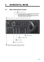
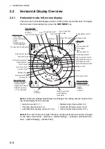


2. HORIZONTAL MODE
2-11
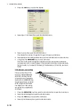
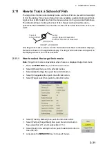
5. Select [Changeable] then push the left-click button.
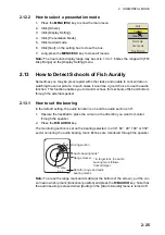
6. Select [Near], [Middle] or [Far] as appropriate then push the left-click button to
change the setting.
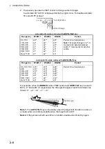
Near: Setting range, 50 - 150 m, 10 m increments. Middle: Setting range, 300 -
500 m, 20 m increments Far: Setting range, 600 - 1000 m, 40 m increments
7. Select [Quit] on the setting box then push the left-click button.
Adjust the TVG level for selected TVG distance as follows.
8. Select [TVG-Near], [TVG-Medium] or [TVG-Far] as appropriate then push the left-
click button.
9. Select
or
as appropriate then push the left-click button to change the setting.
The setting range is -5 to 5. The higher the setting value, the higher the gain. For
strong echoes, such as sea surface reflections or plankton, lower the setting by 1
or 2.
10. Select [Quit] on the setting box then push the left-click button.
11. Long-press the
MENU/ESC
key to close all menus.
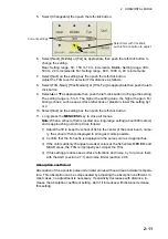
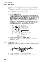
Note:
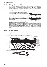
When a school of fish is located on a long-range setting (about 800 meters)
and is approaching own ship do as follows:
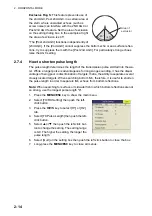
1) Adjust the tilt to keep the school of fish in the center of the sonar beam, name-
ly, the school of fish is displayed in strongest colors possible.
2) Confirm that the fish echo is displayed in the same color as it approaches.
3) If the color suddenly changes to weaker colors as the fish enters MEDIUM and
NEAR areas, the TVG is improperly set. Adjust the TVG.
4) If this setting produces sea surface reflections and noise, try to remove them
with the AGC (section 2.7.1) and noise limiter (section 2.9.5.
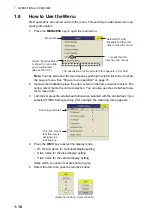
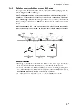
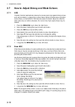
Absorption coefficient
Attenuation of the acoustic pulse underwater varies with sea area and water tempera-
ture. This absorption can be compensated by adjusting the absorption coefficient. In
most cases, no adjustment is necessary. If sensitivity decreases with distance, in-
crease the absorption coefficient setting. And if it increases with distance decrease
this setting.
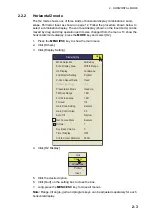
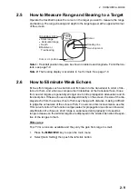
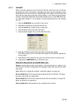
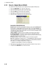
Current settings
Select item with trackball;
push left-click button to adjust.
Summary of Contents for FSV85MK2
Page 12: ...SYSTEM CONFIGURATION xii This page is intentionally left blank ...
Page 74: ...2 HORIZONTAL MODE 2 44 This page is intentionally left blank ...
Page 128: ...4 SLANT MODE 4 36 This page is intentionally left blank ...
Page 132: ...5 NUMERIC GRAPHIC DATA DISPLAY 5 4 This page is intentionally left blank ...
Page 188: ...9 MAINTENANCE 9 24 This page is intentionally left blank ...
Page 199: ......


