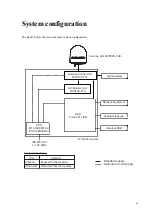
FV-110GX system
1-7
1.1.4
GX Modem Unit (GMU)
The GMU is the modem in the system. The GMU comes in a 19” rack version.
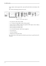
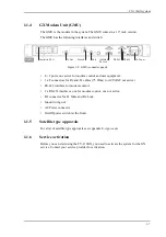
The GMU has the following interfaces and switch:
• 8 + 2 ports, one active for modem control and user equipment.
• 3 x F connectors for Rx and Tx cables (75 Ohm) to ACU (Rx2 not active)
• RS-422 interface for modem control.
• 2 x RS-232 interfaces, one for modem control, one not active.
• I/O connector for Tx Mute and Rx Lock.
• Ground wing nut.
• AC Power connector.
• On/Off power switch (at the front).
1.1.5
Satellite type approvals
For a list of satellite type approvals see Appendix E,
Approvals
.
1.1.6
Service activation
Before you can start using the FV-110GX, you need to activate the system for the GX
service. Contact your service provider for activation.
Figure 1-8: GMU (connector panel)
Control via ACU
Tx Out
Ground
Rx In
Tx Mute &
Rx Lock
RS-232
RS-422
AC Power
Summary of Contents for FV-110GX
Page 1: ...GX TERMINAL FV 110GX OPERATOR S MANUAL www furuno com Model ...
Page 16: ...xiv This page is intentionally left blank ...
Page 46: ...Installation of the ADU 2 22 N connector interface on the ADU ...
Page 54: ...To connect the ADU ACU and GMU 2 30 This page is intentionally left blank ...
Page 110: ...Installation check list Functional test in harbor 6 4 This page is intentionally left blank ...
Page 164: ...Supported commands C 10 This page is intentionally left blank ...
Page 165: ...D 1 Appendix D Approvals D This appendix lists the approvals for FV 110GX OEM declaration ...
Page 166: ...OEM declaration D 2 D 1 OEM declaration ...
Page 173: ...OD 1 30 Jul 2018 H MAKI ...
Page 174: ...OD 2 30 Jul 2018 H MAKI ...
Page 175: ...OD 3 2 Oct 2018 H MAKI ...
Page 176: ...OD 4 2 Oct 2018 H MAKI ...
Page 178: ......
Page 186: ......

