background image

Site preparation


2-7

2.2.5

Ship motion and offset from the ship’s motion centre

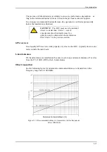
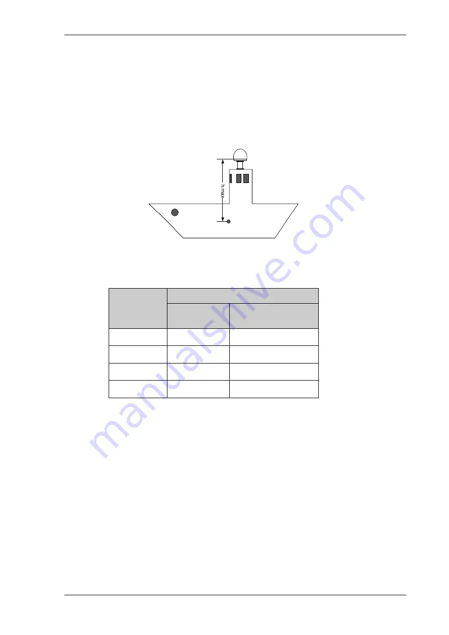
When installing the ADU you must consider the mounting height carefully. The higher up 
the ADU is mounted, the higher is the linear g force applied to the ADU. The g force also 
depends on the roll period of the ship, see Table 2-1. If the g force applied is too high, 
performance and ADU signal stabilization may be reduced and eventually the ADU may 
be damaged. See the following table for allowed mounting heights above the ship’s 
motion centre. 

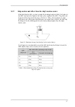
Even though it is recommended to mount the ADU high, keep the distance between the 
ADU and the ship’s motion centre as short as possible. 

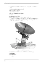
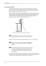
Figure 2-5: Maximum distance from the ship’s motion centre (h max)

Min. 

roll period

Maximum ADU mounting height (h max)

Full 

performance

Potential risk of damage

4 s

12 m

16 m

6 s

27 m

35 m

8 s

48 m

62 m

10 s

75 m

98 m

Table 2-1: Maximum distance from the ship’s motion center versus 

ship’s roll period

Summary of Contents for FV-110GX

Page 1: ...GX TERMINAL FV 110GX OPERATOR S MANUAL www furuno com Model ...

Page 2: ...al is elemental chlorine free FURUNO Authorized Distributor Dealer 9 52 Ashihara cho Nishinomiya 662 8580 JAPAN A MAY 2017 Printed in Japan All rights reserved D MAR 05 2019 Pub No OME 57030 D YOTA FV 110GX 0 0 0 1 9 4 0 6 0 1 3 ...

Page 3: ...us in the ACU display must show TRACKING and the upper status line MDM NETOK i Configuration task What to do and where to find more information Heading input Configure the heading input to External under SETTINGS Navigation For more information see Select the desired heading input see the following table on page 5 4 Connect the ship s heading RS 422 NMEA0183 to the NMEA 0183 multi connector Pin 8 ...

Page 4: ...d trademarks or service marks of their respective holders How to discard this product Discard this product according to local regulations for the disposal of industrial waste For disposal in the USA see the homepage of the Electronics Industries Alliance http www eiae org for the correct method of disposal How to discard a used battery Some FURUNO products have a battery ies To see if your product...

Page 5: ...an result Indicates a condition that can cause death or serious injury if not avoided Indicates a condition that can cause minor or moderate injury if not avoided WARNING WARNING If you feel the equipment is acting abnormally or giving off strange noises immedi ately turn off the power at the switchboard and contact a FURUNO service technician Do not disassemble or modify the equipment Fire electr...

Page 6: ... being installed Ensure the unit is properly grounded Improper grounding can cause electrical shock or interference from with other devices Use equipment with a suit able voltage rating for ship s mains Rated voltage is directed at each unit and out of range voltage may cause damage to the equipment Do not approach the FV 110GX antenna unit when it is trans mitting The radome emits radio waves tha...

Page 7: ...2 1 2 Initial inspection 2 2 2 1 3 Tools needed 2 2 2 1 4 Transport of the antenna 2 2 2 2 Site preparation 2 3 2 2 1 General site considerations 2 3 2 2 2 Obstructions ADU shadowing 2 4 2 2 3 Blocking zones with azimuth and elevation 2 5 2 2 4 Safe access to the ADU radiation hazard 2 6 2 2 5 Ship motion and offset from the ship s motion centre 2 7 2 2 6 Mast foundation and height 2 8 2 2 7 Inter...

Page 8: ...onnector 3 2 3 1 3 ADU connector 3 2 3 1 4 Rx In and Tx Out connectors 3 2 3 1 5 NMEA 0183 connector 3 3 3 1 6 RS 232 and RS 422 connectors 3 4 3 1 7 LAN1 4 connectors 3 5 3 2 Interfaces of the GMU 3 6 3 2 1 Connector panel 3 6 3 2 2 Rx In and Tx Out connectors 3 6 3 2 3 RS 232 and RS 422 connectors 3 7 3 2 4 LAN connectors 8 2 3 8 3 2 5 I O connector for Tx Mute and Rx Lock 3 8 Chapter 4 Power an...

Page 9: ... with the web interface 5 15 5 4 1 Overview and dashboard 5 15 5 4 2 To set up blocking zones RX and TX 5 20 5 4 3 To configure the LAN network 5 23 5 4 4 E mail setup 5 25 5 4 5 Setup of reports syslog and SNMP traps 5 26 5 4 6 Administration 5 31 5 5 Keypad and menus of the ACU 5 36 5 5 1 ACU display and keypad 5 36 5 5 2 Navigating the menus 5 37 5 5 3 The menu tree 5 38 5 5 4 Brightness of the...

Page 10: ... 7 4 2 LEDs in the ACU 7 16 7 4 3 LEDs of the GMU 7 16 7 5 Removal and replacement of the ACU and GMU 7 17 7 6 Removal and replacement of ADU modules 7 17 7 7 Troubleshooting 7 20 7 7 1 Overview 7 20 7 7 2 Event list for troubleshooting 7 20 7 7 3 Diagnostics report for troubleshooting 7 20 7 8 To return units for repair 7 20 Appendix A Ground and RF protection A 1 Why is a ground connection requi...

Page 11: ...stem messages B 1 Event messages overview B 1 B 2 List of ADU events B 2 B 3 List of ACU events B 8 Appendix C Command line interface C 1 Introduction C 1 C 1 1 Telnet connection C 1 C 1 2 Help C 2 C 1 3 Conventions C 2 C 2 Supported commands C 2 C 2 1 config C 3 C 2 2 demo C 3 C 2 3 exit C 3 C 2 4 help C 3 C 2 5 modem C 4 C 2 6 satellite C 4 C 2 7 status C 7 C 2 8 system C 7 C 2 9 track C 8 C 2 1...

Page 12: ...e operation SNMP support Remote or local simultaneous software update of ADU ACU and GMU via PC and Internet browser Global RF configuration Full remote control and troubleshooting with built in test equipment BITE ACU with 4 x LAN NMEA 0183 NMEA 2000 RS 232 and RS 422 AC powered GMU with 8 2 LAN RS 232 and RS 422 and I O connector No scheduled maintenance Software version This manual is intended ...

Page 13: ... Unit 407009C FUR Antenna Control Unit 407016C F19 GX Modem Unit 407023A F19 NSD Cisco 2911 ISR UPS E11A102B001UJ E11A102B002UJ 100 240V AC 1ø 50 60Hz Analog Telephone Network Equipment Gyrocompass 19 Rack Console Equipment category Unit Category Antenna Other units Exposed to the weather Protected from the weather Inmarsat FBB ...

Page 14: ...stallation materials included See PL 4 Installation Materials CP16 04200 000 015 931 Select one 30 m 8D FB CV cable single connector CP16 04120 000 015 865 40 m 8D FB CV cable single connector CP16 04210 000 015 932 50 m 8D FB CV cable single connector CP16 04220 000 029 109 60 m 8D FB CV cable single connector CP16 06200 For current antenna 000 029 423 Select one For 100 ACV See PL 5 CP16 06210 F...

Page 15: ...xiii Optional supply Name Model Code No Remarks UPS E11A102B001UJ For 100 110 115 120 VAC E11A102B002UJ For 200 220 230 240 VAC Jumper Cable 407090A 925 001 423 890 ...

Page 16: ...xiv This page is intentionally left blank ...

Page 17: ...the coverage map of the GX service at global service introduction The FV 110GX system consists of the following units Above Deck Unit ADU Antenna Control Unit ACU GX Modem Unit GMU The system only requires a single 50 Ohm cable to provide the Above Deck Unit ADU with both DC power data and control information The radome does not have to be removed neither before nor after the installation To prote...

Page 18: ... environments with elevations of 25 to 125 The ADU weighs 126 kg and is powered by the ACU The ADU is protected by a radome All communication between the ADU and the ACU passes through a single standard 50 Ohm cable with N connector through the rotary joint No cable work is required inside the radome There are two types of antenna new antenna and current antenna Figure 1 2 ADU ACU and GMU Above De...

Page 19: ...M3 3 Pedestal Control Module PCM2 4 Service switch 5 Single Motor Driver Module for cross elevation SMD used DDM in log 6 Cross elevation motor and encoder 7 Zero Reference Module x3 ZRM not visible on photo 2 in the figure above 1 in the figure below Figure 1 4 Above Deck Unit modules 1 2 ...

Page 20: ...nertial Sensor Module ISM 15 Elevation locking pin to lock the antenna dish in a fixed position In switch off position the Single Motor Driver modules SMD used DDM in log and the BUC are turned off for safe conditions during service and repair The switch must be set to on for normal operation 16 Single Motor Driver Module for Azimuth SDM used DDM in log 17 Azimuth motor 18 Azimuth encoder 19 Rotar...

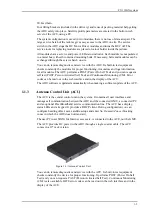
Page 21: ... Activated Self Test and Continuous Monitoring CM Error codes can be read out in the web interface and in the display of the ACU The ADU software is updated automatically when making a software update of the ACU 1 1 3 Antenna Control Unit ACU The ACU is the central control unit in the system It contains all user interfaces and manages all communication between the ADU and the connected GMU a conne...

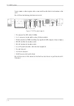
Page 22: ...EA interfaces for input from GPS compass or Gyro compass RS 422 interface for modem control RS 232 interface for modem control 4 x LAN ports for modem control and user equipment Ground wing nut AC Power connector On Off power switch at the front The ACU has also a LAN connector at the front to access the service port from the ACU front panel Figure 1 7 ACU connector panel 1 6HUYLFH WR IURQW 7 Q 5 ...

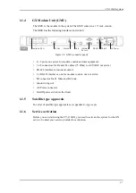
Page 23: ... x RS 232 interfaces one for modem control one not active I O connector for Tx Mute and Rx Lock Ground wing nut AC Power connector On Off power switch at the front 1 1 5 Satellite type approvals For a list of satellite type approvals see Appendix E Approvals 1 1 6 Service activation Before you can start using the FV 110GX you need to activate the system for the GX service Contact your service prov...

Page 24: ...ns for FV 110GX The following options are available for the FV 110GX system Part number Description 407009C FUR 01 Above Deck Unit ADU 407016C F19 Antenna Control Unit ACU 407023A F19 Global Xpress Modem Unit GMU Table 1 1 Part numbers for the FV 110GX system Part number Description 407090A 925 Pigtail Cable 1 25 m N Conn female male Table 1 2 Part numbers for options of the FV 110GX system ...

Page 25: ...present FV 110GX ADU with 4 lifting brackets already mounted Accessory kit for FV 110GX ADU Package with bolts washers and cable glands 2 sizes FV 110GX ACU Accessory kit for FV 110GX ACU NMEA multi connector Power cable 230 VAC RJ45 patch cable 1 pce Coax cable F F low loss 75 Ohm 2 pcs Ethernet cable 2 m 1 pce FV 110GX GMU Accessory kit for FV 110GX including Wiecon 3 5 mm spacing 4 pol connecto...

Page 26: ...co included mounted on a tool holder inside the ADU radome Torx TX 20 to open the locks of the service hatch Wrench to fasten the mounting bolts for the ADU Wrench to fasten the N connector at the ADU PC and Internet browser Crimping tools 2 1 4 Transport of the antenna During transport the antenna must be able to move freely inside the radome You must follow the instructions below to keep a valid...

Page 27: ...rations You do not have to align the ADU with the bow to stern line of the ship When configuring the FV 110GX the azimuth calibration provides the correct azimuth of the ADU Painting the radome Customers may wish to paint the radome in order to match the vessel s colour Cobham SATCOM s recommendation is that the radome should NOT be painted because it may impact RF performance and may lead to over...

Page 28: ...tc within this field can cause signal degradation or signal loss For optimum performance adhere to the following guidelines 1 Place the ADU so that it has as much free line of sight as possible without any structures in the beam through one full 360 degrees turn of the vessel 2 Do not place the ADU close to large objects that may block the signal 3 Elevate the ADU by mounting it on a mast or on a ...

Page 29: ...ns frequently being in these zones You can set up 8 blocking zones Each blocking zone is set up with azimuth start and stop and elevation angle The blocking zones are set up in the built in web interface of the ACU during configuration For further information see To set up blocking zones RX and TX on page 5 20 Figure 2 2 2 blocking zones with no transmit zones azimuth example Figure 2 3 Blocking z...

Page 30: ...tes up to 54 5 dBW EIRP This translates to a minimum safety distance of 30 m from the ADU while it is transmitting based on a radiation level of 10 W m2 Figure 2 4 Radiation hazard safety distance 30 m MICROWAVE RADIATION NO PERSONNEL within safety distance of 30 m based on 10 W m2 ...

Page 31: ...ization may be reduced and eventually the ADU may be damaged See the following table for allowed mounting heights above the ship s motion centre Even though it is recommended to mount the ADU high keep the distance between the ADU and the ship s motion centre as short as possible Figure 2 5 Maximum distance from the ship s motion centre h max Min roll period Maximum ADU mounting height h max Full ...

Page 32: ...he mast flange do as follows 1 Fit the top of the ADU mast with a flange with clearance holes matching the bushings in the radome and with minimum 4 gusset plates No center hole is necessary in the flange Flange thickness Minimum 15 mm 4 gusset plates Minimum 15 mm thick must be placed close to the holes in the mounting plate and evenly distributed 2 Make sure that the recommended flatness on the ...

Page 33: ...irect contact with the radome Round all edges as much as possible to avoid damaging the surface of the radome Figure 2 8 ADU mast flange distance to the welded seam Figure 2 9 ADU bottom view 50 Welded seam Welded seam Gusset plate Allow sufficient space so the nut is free of the welded seam and there is room for tools min 50 mm Clearance hole for M12 bolts New antenna Current antenna R326 248 ø35...

Page 34: ...ze the mast further The tables in the next sections give suggested design values for the free mast length The following tables show the minimum dimensions for a ADU mast with and without stays or wires Note that the values are only guidelines always consider the environment and characteristics of the ship before deciding on the mast dimensions Figure 2 10 Free mast length and bracing for a tall ma...

Page 35: ...hatch difficult 200 5 24 0 0 6 220 5 26 5 0 8 250 5 30 2 1 270 5 32 7 Table 2 2 Mast dimensions without braces Mast with 3 braces Max free mastlength steel m Outer Diameter mm Wall Thickness mm Outer Diameter for brace mm Thickness for brace mm 1 2 140 10 50 5 0 1 2 200 5 50 5 0 1 6 140 10 70 5 0 1 6 200 5 70 5 0 2 160 10 70 5 0 2 220 5 70 5 0 2 5 180 10 80 5 0 2 5 220 5 80 5 0 Table 2 3 Mast dime...

Page 36: ...with 2 braces Max free mast length steel m Outer Diameter mm Wall Thickness mm Outer Diameter for brace mm Thicknes s for brace mm 1 2 160 10 80 5 0 1 2 200 5 80 5 0 1 6 180 10 80 5 0 1 6 220 5 80 5 0 2 180 10 80 5 0 2 240 5 80 5 0 2 5 200 10 80 5 0 2 5 260 5 80 5 0 Table 2 4 Mast dimensions with 2 braces Figure 2 11 Free space for access to the service hatch New antenna Current antenna ...

Page 37: ...s a fan beam with a horizontal beam width of a few degrees and a vertical beam width of up to 15 you can avoid the worst interference by mounting the ADU at a different level meaning that the ADU is installed minimum 15 above or below the radar antenna Due to near field effects the benefit of this vertical separation could be reduced at short distances below approximately 10 m between radar antenn...

Page 38: ...ence of one or more S or X band radars within a radius up to 100 m may cause a minor degradation of the Ka band connection The degradation will be most significant at high radar pulse repetition rates As long as receiving conditions are favourable this limited degradation is not important However if receiving conditions are poor e g due to objects blocking the signal path heavy rainfall or icing l...

Page 39: ...own to one meter outside the main beam L band antennas If L band antennas are installed on the same vessel keep a minimum distance of 3 metres from the FV 110GX ADU to the L band antenna Other transmitters See the following figure for minimum recommended distance to transmitters in the frequency range below 1000 MHz CAUTION The ADU must never be installed closer to a radar than d min even if exper...

Page 40: ...uch that direct spray of seawater is avoided 2 Make sure the ADU s drain tube is open and that there it free space between the drain tube and the mounting surface so water can escape and there is ventilation for the ADU 3 Do not use pneumatic tools for cleaning the radome especially at a short distance and directly at the split between top and bottom 4 Do not place the ADU close to a funnel as smo...

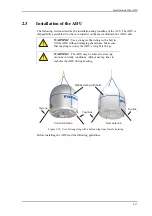
Page 41: ... the following guidelines WARNING Use a strong webbed sling with a belt to lift the ADU without damaging the radome Make sure that the sling can carry the ADU s weight 126 kg WARNING The ADU may be subject to swaying motions in windy conditions Always use tag lines to stabilise the ADU during hoisting Figure 2 15 Use of strong sling with a belt and tag lines for safe hoisting Current antenna New a...

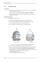
Page 42: ...ooden top and remove the casing 3 Unscrew the 4 bolts holding the ADU on the wooden platform 4 Attach a webbed four part sling with a belt to all 4 lifting brackets Figure 2 16 ADU installation webbed sling attached to the 4 lifting brackets 5 Attach 2 tag lines of suitable length to 2 lifting brackets and man them 6 With a crane lift the ADU off the wooden platform and move it on top of the ADU m...

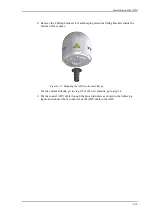
Page 43: ...kets inside the bottom of the radome For the current antenna go to step 9 For the new antenna go to step 14 9 Put the coaxial ADU cable through the protection plate as shown in the following figure and connect the N connector of the ADU cable to the ADU Figure 2 17 Mounting the ADU on the mast flange ...

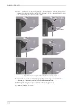
Page 44: ...nnect the N connector on the ADU Figure 2 18 Connecting the ADU cable for the current antenna 11 Ensure that the connector assembly is properly protected against seawater and corrosion As a minimum wrap it with self amalgamating rubber 12 Put the protection plate in place and fasten the 4 bolts picture 5 13 Fasten the nut Go to step 16 N connector N connector 1 2 Protection plate Protection plate ...

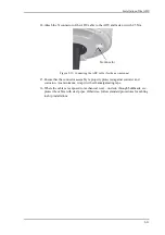
Page 45: ...erly protected against seawater and corrosion As a minimum wrap it with self amalgamating tape 16 Where the cables are exposed to mechanical wear on deck through bulkheads etc protect the cables with steel pipes Otherwise follow standard procedures for cabling in ship installations Figure 2 19 Connecting the ADU cable for the new antenna 2 4 N connector ...

Page 46: ...Installation of the ADU 2 22 N connector interface on the ADU ...

Page 47: ...the latches 2 Pull open the two latches and let the lid fall open Figure 2 20 To open the service hatch If necessary you can remove the service hatch 3 Free the service hatch from the nylon loops move them to the side one by one Figure 2 21 To remove the nylon loops 4 Pull the service hatch free The service hatch weighs approx 4 5 kg 5 When inserting the hatch again follow steps above in reverse o...

Page 48: ...a 1 With a Torx TX 30 screw driver loosen the 8 screws that keep the hatch in place 2 Lower the service hatch and let it hang in the 2 strips 3 Pull the service hatch free The service hatch weighs approx 2 5 kg Figure 2 22 To open the service hatch ...

Page 49: ...to the bolt marked in the figure below Figure 2 23 ADU bolt for optimum grounding If the ADU cannot or should not be electrically connected directly to the mounting surface you can use a separate grounding cable to make the connection between the ADU and the common ground to which the ACU is also connected If grounding to the ship ground is impossible for example if you have a fibre glass hull see...

Page 50: ...re fulfilled 1 Check the data sheet from the cable supplier to verify the values The RF attenuation and the DC resistance are below the maximum values specified below ADU cable RF attenuation at 1950 MHz Max 20 dB including connector ADU cable RF attenuation at 4450 MHz Max 35 dB including connector ADU cable modem attenuation at 10 MHz Max 2 dB ADU cable modem attenuation at 36 and 54 MHz Max 4 d...

Page 51: ...ort bracket according to the requirements for your 19 rack 3 Connect all cables See Interfaces of the ACU on page 3 1 for a description of the ACU connectors 2 4 2 To ground the ACU To ground the ACU do as follows 1 Make sure that the grounding requirements are met See the appendix Ground and RF protection on page A 1 for details about grounding 2 You must ground the ADU cable coax cable with an N...

Page 52: ...ambient temperature 2 5 1 To install the modem To install the GMU do as follows 1 Slide the GMU into a 1U space in a 19 rack preferably directly below or above the ACU 2 Mount the screws in each side through the holes in the front and fasten the screws to the rack Make sure that the unit is mounted securely using the optional support bracket according to the requirements for your 19 rack For infor...

Page 53: ...e following figure shows how to connect the ADU ACU and GMU 1 Connect the antenna cable to Antenna at the ACU and the antenna 2 Connect Rx Out at the ACU to Rx In at the GMU with the supplied cable 75 Ohm coax F F 1 m 3 Connect Tx In at the ACU to Tx Out at the GMU with the supplied cable 75 Ohm coax F F 1 m 4 Connect RS 232 on the ACU to RS 232 right at the GMU 5 Connect RS 422 on the ACU to RS 4...

Page 54: ...To connect the ADU ACU and GMU 2 30 This page is intentionally left blank ...

Page 55: ...ector panel of the ACU The connector LAN on the front panel is typically connected to the service port at LAN3 with a straight Ethernet cable Then you can access the service port from the front of the ACU rack version Figure 3 1 ACU LEDs display and keypad detailed example 0DLQ 1 9 0 0 1 72 1 75 1 6 7 5 7 0 5 Figure 3 2 ACU connector panel 1 6HUYLFH WR IURQW 7 Q 5 2XW URXQG 1 1 0RGHP FRQWURO 56 10...

Page 56: ...onnect the ACU to the GMU Outline on the ACU Voltage range 100 240 VAC Table 3 1 AC power connector N P Earth Outline on the ACU Conductor Pin function Inner DC to ADU reference clock to ADU ACU to ADU internal communication GX Rx Tx Outer GND Shield Table 3 2 N connector outline and pin assignment Important Do not use TNC connectors on the ADU antenna cable or on pigtails TNC connectors cannot ca...

Page 57: ...grated Instrument HCHDT Magnetic compass Recommended NMEA 0183 cable Two wire constructed with one enclosed shield Network signal pair Size No 24 AWG 0 24 sq mm or heavier 1 Hardware prepared for NMEA 2000 for future use NMEA 2000 power 9 16 VDC NMEA 2000 LEN Load Equivalency Number 2 100mA Outline on the ACU Pin Pin function Wire color 1 Not connected 2 NET H NMEA 2000 White 3 NET L NMEA 2000 Blu...

Page 58: ...rs to connect the ACU to the GMU Outline on the ACU Pi n Pin function 1 Not connected 2 RXD 3 TXD 4 DTR 5 Ground 6 DSR 7 RTS 8 CTS 9 Receive Signal Strength Indicator Table 3 5 RS 232 connector male outline and pin assignment ACU Outline on the ACU Pin Pin function 1 Ground 2 Line A RXD 3 Line B TXD 4 Ground 5 Ground 6 Not connected 7 Line A RXD 8 Line B TXD 9 Not connected Table 3 6 RS 422 connec...

Page 59: ...N Internet etc 3 Connect an Ethernet cable to Port 3 and to the LAN connector on the left side of the rear panel if you want to use the front LAN connector of the ACU for system control 4 Use Port 4 network 3 to connect the FV 110GX to the vessel s LAN For more details about the LAN networks see To configure the LAN network on page 5 23 Outline Pin Pin function Wire color 1 Tx White orange 2 Tx Or...

Page 60: ...ector panel of the GMU 3 2 2 Rx In and Tx Out connectors The GMU has an Rx In and a Tx Out connector Use these connectors to connect the ACU to the GMU Figure 3 3 GMU connector panel Control via ACU Tx Out Ground Rx In Tx Mute Rx Lock RS 232 RS 422 AC Power Outline on the ACU Pin number Pin function 1 Inner conductor 50 MHz clock Rx Tx 2 Outer conductor GND Shield Table 3 8 F connector Rx and Tx o...

Page 61: ...o the GMU Outline on the GMU Pi n Pin function 1 Not connected 2 BUC TXD 3 BUC RXD 4 Not connected 5 GND 6 Power good 7 GMU reset 8 Temperature out of range 9 Core module RSS Table 3 9 RS 232 connector male outline and pin assignment GMU Outline on the GMU Pin Pin function 1 GND 2 Keyline P 3 Reset P 4 GND 5 GND 6 Not connected 7 Keyline N 8 Reset N 9 Not connected Table 3 10 RS 422 connector male...

Page 62: ...CAT5 shielded For outline and pin allocation see figure 3 7 on page 3 5 3 2 5 I O connector for Tx Mute and Rx Lock The GMU has one I O connector for Tx Mute and Rx Lock Figure 3 4 LAN connectors at the GMU Port 1 modem control connects to the ACU Port 1 Port 2 Port 3 Port 4 Port 5 Port 6 Port 7 Port 8 Port 9 Port 10 Outline on the GMU Pin Pin function 1 GND 2 Not connected 3 Rx Lock out 4 Tx Mute...

Page 63: ... to the GMU 2 Connect the power cable to the GMU 4 2 2 Power up procedure 1 Switch on the ACU The unit starts up and goes through an initialization procedure ACU POST Antenna Initializing Antenna POST READY This may take some time up to a couple of minutes 2 The FV 110GX is ready to be calibrated for first time power up or receive data from the GMU when in normal operation Figure 4 1 ACU to connec...

Page 64: ...h on the GMU For more detailed step by step instructions see the chapter Configuration on page 5 1 4 2 3 Initialisation steps in daily use Once the system is configured and a satellite profile is active the startup sequence is as follows ACU POST Antenna Initializing Antenna SW upload If the software versions in the ADU and ACU are not the same a software update is done during startup Antenna POST...

Page 65: ...ace To connect to the web interface of the ACU do as follows 1 Switch on the ACU Wait until the LEDs on the front plate of the ACU show that the system is ready to be configured Power LED Green Logon LED Off Fail Pass LED Flashing green during power on self test after that steady green 2 Connect a PC to LAN port 3 Service standard Ethernet of the ACU or to the front LAN connector of the ACU Import...

Page 66: ...event text 0807F 0 WARNING Local administration enabled This will give you temporary administrator access for 1 hour or until next restart 3 Open your browser and access the web interface 4 Enter user name admin no password is required The DASHBOARD is displayed 5 To enter or change the password select ADMINISTRATION User login and locate the section Change Login 6 If needed type in the new passwo...

Page 67: ...Introduction to the built in web interface 5 3 The web interface shows the DASHBOARD page For a detailed introduction to the web interface see Overview and dashboard on page 5 15 Figure 5 3 Dashboard ...

Page 68: ...ant Make sure that the modem is switched off at this point Switch on the modem after the cable calibration Important You must be logged on as an administrator See Import a configuration from file see section above on page 5 35 Heading input Description External Heading input from the vessel s gyro compass default If there is no heading input due to failure alarms are raised and the antenna continu...

Page 69: ...None Important You must make an azimuth and cable calibration with Fixed before you can use this setting This is required in order to be able to use blocking zones After a successful azimuth and cable calibration you must change the heading input setting from Fixed to None Select this setting after a successful azimuth calibration with Fixed heading if the system does not have input from the vesse...

Page 70: ...ntenna checks each stored position for up to 10 seconds If RX lock is detected for more than 20 of the time the antenna goes to Tracking Without heading input and not fixed heading Gyro free 1 A box search pattern is started and the positions with reception of RF power are checked for up to 10 seconds If RX lock is detected for more than 20 of the time the antenna goes to Tracking Figure 5 6 Acqui...

Page 71: ...ion Azimuth calibration is done toward a satellite of a known position After finding the satellite the system can calculate the azimuth offset of the ADU installation The satellite and transponder properties for the calibration can be selected from a list of service profiles or supplied manually You can make an azimuth calibration in the following ways Azimuth calibration user controlled Automatic...

Page 72: ...rtant to supply the correct longitude including the first decimal Important It is strongly recommended to verify the result of a calibration performed with user defined data This can be done by making a new calibration on a different satellite and verify that the resulting Azimuth calibration value differs less than one degree Error code Explanation 1 The elevation of the selected satellite is too...

Page 73: ... makes the azimuth calibration After a successful azimuth calibration the ACU will automatically disable the Azimuth calibration active satellite profile on the page SERVICE Calibration 1 Create a modem profile see Modem profiles on page 7 13 2 Create a satellite profile see Satellite profiles on page 7 12 3 Click SETTINGS and Activate the satellite profile 4 Click SERVICE Calibration Figure 5 7 W...

Page 74: ...lite parameters directly on the calibration page use this calibration method To prepare for calibration you can set up a service profile for calibration To setup a service profile do as follows 1 Connect a PC to LAN connector 3 Service port standard Ethernet of the ACU or to the front LAN connector of the ACU 2 Open an Internet browser and enter the IP address of the ACU Default http 192 168 0 1 3...

Page 75: ...ble is still in good order 4 After the azimuth and cable calibration switch on the modem It will automatically make a BUC calibration and is then ready 5 When commissioning is completed test all subscribed services see Installation check list Functional test in harbor on page 6 3 1 Use Orbital position and NID if you want to use NID or orbital position or other KA band satellites with DVB S2 suppo...

Page 76: ...ACU display This may take up to 10 minutes If a new cable calibration is made the ACU displays the alarm BUC calibration outdated Then you must make a manual One Touch Commissioning To make a manual One Touch Commissioning OTC for the modem do as follows 1 Connect a PC to LAN1 2 Enter the web interface via Firefox browser and go to SERVICE Modem Figure 5 10 Web interface SERVICE Modem 3 At Modem a...

Page 77: ...put from a gyro compass is not available Heading input none information from the GPS position is used when searching for a satellite If the antenna does not have ship heading input from the vessel s gyro compass the azimuth direction of the satellite is not known In this case the antenna will start a 360 degrees sky scan and scan until it finds a satellite The search time to find the satellite and...

Page 78: ...IF gain independent of antenna cable length1 Compatibility with the GX TX Power control feature When installing the FV 110GX you make a cable calibration At that point every installation adjusts to the same average TX IF gain regardless of the ADU cable length Additionally the FV 110GX system also compensates for variations of the cable characteristics or loss over frequency 1 You find the maximum...

Page 79: ...s You can click on each menu in the site map to go directly to the page or display the respective submenu The Dashboard is the first screen that is displayed when the user or administrator enters the IP address of the web interface of the ACU The Dashboard is used for viewing properties and status of the ACU and ADU The web interface consists of the following sections Figure 5 12 Topics in the web...

Page 80: ...e events when relevant The host name is shown on every page of the web interface 4 The host name is useful for identifying the system at remote login and when requesting reports from the system The host name is recommended to contain the name of the vessel To change the host name see To configure the LAN network on page 5 23 5 The contents section shows the page selected in the navigation pane Thi...

Page 81: ...cording to your network requirements See To configure the LAN network on page 5 23 for more information 2 Open your Internet browser and enter the IP address of the ACU Default IP address http 192 168 0 1 Status field in the icon bar The top bar shows the current status of the antenna Antenna initializing Antenna SW upload Antenna POST error XIM data error Unrecoverable XIM data error System upgra...

Page 82: ...blocking zone No TX zone antenna is pointing in a no TX zone TX is off Information fields on the Dashboard DASHBOARD Description GNSS position Current position of the vessel reported by the GNSS module Vessel heading Ship s heading in degrees with reference to North provided by the ship s gyro Satellite profile Name of the currently active satellite profile Satellite position Position of the satel...

Page 83: ...50 MHz reference signal on its TX connector On and if an iDirect OpenAMIP modem indicates modem Locked and Tx ON in the OpenAMIP message L L 1 1 Table 5 7 Web interface DASHBOARD MODEM section POINTING Description Azimuth elevation geo Current value for azimuth elevation relative to the vessel heading Azimuth elevation rel Current value for azimuth elevation relative to the vessel Table 5 8 Web in...

Page 84: ...s and elevation angles for each blocking zone Azimuth values and elevation angles for each blocking zone can be entered To enable a blocking zone you must select Active To define and set a blocking zone do as follows 1 Select SETTINGS Blocking zones 2 Select Active to enable the blocking zone Figure 5 14 Web interface SETTINGS Blocking zones azimuth and elevation ...

Page 85: ...angle for the blocking zone If you enter nothing there will be no blocking zone Values allowed 90 to 90 degrees 5 Select No TX for zones if you don t want the system to transmit Figure 5 15 Blocking zone example 315 45 degrees Figure 5 16 Blocking zone example 45 315 degrees Important You must enter 2 different elevation angles to have an active blocking zone QWHQQD ORFNLQJ RQH QWHQQD ORFNLQJ RQH ...

Page 86: ...is defined with TX allowed No TX not checked the modem is not informed about the blocking zone Modems may react differently when informed about a blocking zone this has influence on recapturing the link The worst case is that the modem will search the entire list of available satellites and frequencies when unaware of the blocking zone resulting in prolonged down times until the link is recaptured...

Page 87: ...three groups each group operating in its own network You can setup DNS and Gateway To configure the LAN network go to SETTINGS Network Important The FV 110GX system is not designed to be connected directly to the Internet It must be located behind a dedicated network security device such as a fire wall If any ports of the FV 110GX are exposed to the Internet you must change the default passwords a...

Page 88: ...addresses Important Make sure that the networks do not use IP address ranges that overlap Sections Preferred use NETWORK Host name The host name is used for identifying the ACU in local networks and in e mail reports The default host name is acu You can change the name Letters a z digits 0 9 and hyphen are allowed as legal characters Note The host name must start with a letter LAN Port 1 This netw...

Page 89: ...n LAN ports 1 3 and 4 you can choose to add a zeroconf address in the network 169 254 0 0 This zeroconf address will be in addition to the existing static or DHCP IP address One port at a time can be enabled Zeroconf allows devices to connect to a network automatically 5 4 4 E mail setup To be able to send diagnostics and statistics reports through an external Internet connection using e mail you ...

Page 90: ...nostic reports at fixed intervals The diagnostic report contains information from the ADU and ACU that are relevant for the service personnel during troubleshooting The report contains data for the selected download intervals To set up sending a statistics report do as follows 1 Select SETTINGS Reporting 2 In the section DIAGNOSTICS REPORT enter the following E mail sender E mail recipients comma ...

Page 91: ...ssed in spreadsheet applications e g Microsoft Excel To set up sending a statistics report do as follows 1 Configure e mail first see E mail setup on page 5 25 2 Go to SETTINGS Reporting 3 In the section STATISTICS REPORT enter the following E mail sender E mail recipients comma separated Send interval Select e mail disabled day default 2 minute samples week hourly samples or month hourly samples ...

Page 92: ...a for a range Antenna Ele degree Antenna Ele Max degree Antenna Ele Min degree Current antenna elevation sample maximum and minimum value for the sampling interval Vsat rx_lo_freq GHz Vsat tx_lo_freq GHz Rx LO frequency of modem for this record Tx LO frequency of modem for this record Tracking rf freq GHz Tracking type Tracking RF frequency for this record Narrow filter DVB S2 decoder and modem RS...

Page 93: ...Save the zipped file to your computer and extract the text file The file name contains the identification of the system example adu acu3_stat_20111021110901_day csv 2 Open the spreadsheet application for example Microsoft Excel 3 On the tab Data click the tab Import from text import the unzipped text file and follow the instructions in the wizard 4 When asked about the delimiter select comma ...

Page 94: ...remote syslog default Off 3 Enter the IP address of the syslog server to which the syslog messages will be sent 4 Click Apply SNMP traps SNMP traps or notifications are network packets which advise the system administrator about significant events in the antenna e g alarms and system error messages They are generated by the antenna and can be sent automatically to an SNMP trap receiver manager To ...

Page 95: ... for authentication of the SNMP trap request 5 Click Apply 5 4 6 Administration In this section of the web interface you can configure the following administrative settings To change the password and log off To set up user permissions for guest login To import and export a system configuration Figure 5 22 Web interface Administration ...

Page 96: ... can log off Figure 5 23 Web interface ADMINISTRATION change administrator logon and password To change the current password do as follows 1 Enter the current password 2 Enter the new password and retype it on the next line 3 Click Change At the next logon the new password is required 4 Click Logoff to log off the system If you have not entered anything for 30 minutes you are logged off automatica...

Page 97: ...gation pane select ADMINISTRATION User permissions 2 For each item under ALLOW USERS TO select Item Description Change network Change IP configuration of the LAN connectors of the ACU For further information see To configure the LAN network on page 5 23 Change e mail settings Change e mail addresses for sending reports For further information see E mail setup on page 5 25 Modify antenna data Only ...

Page 98: ... another FV 110GX or be used as backup The configuration file contains all the settings you have entered during system setup satellite profiles modem profiles LAN setup blocking zones etc Figure 5 26 Web interface ADMINISTRATION Export import configuration Item Description Change network Change IP configuration of the LAN connectors of the ACU For further information see To configure the LAN netwo...

Page 99: ...screen To load a configuration from a file do as follows 1 Select ADMINISTRATION Export import config 2 Click the button Browse and locate the configuration file cfg file you want to upload 3 Click the button Open 4 Click the button Upload To clone a system configuration do as follows 1 Reset to factory default see the following section for details 2 Import a configuration from file see section ab...

Page 100: ... POST SAFE MODE error followed by an error description SERVICE SWITCH service switch in ADU activated READY waiting for data from the modem or no satellite profile selected POINTING ANTENNA locating the satellite ACQUIRING SIGNAL acquiring the satellite signal TRACKING tracks the current satellite AZIMUTH CALIBRATION TX CABLE CALIBRATION BUC CALIBRATION TEST NOT READY waiting for input from GNSS e...

Page 101: ...currently active satellite profile H horizontal V vertical L left hand R right hand 8 RF tracking frequency in GHz and LNB LO Frequency 9 TX Modem TX ADU TX TX pol Modem TX m M ADU TX a A Tx pol H V L R After 1 hour the display is dimmed to lowest intensity Press any key to light up the display 5 5 2 Navigating the menus Use the keypad to navigate the menus Press OK or to select a menu item Use th...

Page 102: ... IP PORT 4 MASK DEFAULT GATEWAY SAT POSITION RX POLARIZATION TX POLARIZATION RX FREQUENCY LNB LO BUC LO EVENT EVENT 1 EVENT 2 EVENT 3 EVENT 4 HOST NAME LOCAL ADMINISTRATION Top level menu Description MAIN View with current status of the FV 110GX Example when logged on to the satellite This view is displayed after a time out of 10 minutes Press any key except left arrow to enter the menu at MAIN Ne...

Page 103: ...ISATION RX POLARISATION LHC or RHC TX POLARIZATION X POL or Co POL GNSS LATITUDE current latitude read from GNSS module LONGITUDE current longitude read from GNSS module FIX TYPE 2D or 3D or NONE HEADING Ship s heading in degrees with reference to North provided by the ship s gyro VERSIONS Current software version SERIAL NUMBERS ACU ACU serial number Antenna Serial number of the antenna LOCAL ADMI...

Page 104: ...ASK 3 LAN 3 Current netmask of the FV 110GX web interface default 255 255 255 0 PORT 4 IP Current IP address for LAN 4 MASK 4 Current netmask for LAN 4 DEFAULT GATEWAY Current default gateway Table 5 18 NETWORK menu of the ACU SATELLITE menu Description POSITION Position of the current satellite RX POLARISATION LHC or RHC TX POLARIZATION X POL or CO POL RX FREQUENCY Ka band receiving frequency of ...

Page 105: ...the following 1 Press and hold and until the ACU display shuts down and the ACU and ADU reboots BUC LO 28 05 GHz system hardware EVENT menu Description EVENT In this menu all active events are listed Use and to go through the active events Events can be of the type WARNING or ERROR If a new event occurs or there is a change in the event list while you are in the EVENTS menu a is shown in the upper...

Page 106: ...lable from the DASHBOARD web pages Detailed documentation about supported OIDs can be found in the FV 110GX MIB file The MIB entries are grouped in the following sections System configuration Navigation coordinates Antenna pointing Dashboard and profile Tracking receiver To get the MIB file do as follows 1 Select HELPDESK 2 Click the link Download MIB file 3 Save the file on your computer Note Non...

Page 107: ...ion on page 2 5 and To set up blocking zones RX and TX on page 5 20 6 Make sure that the safety distance for radiation hazard of 30 metres is kept See Safe access to the ADU radiation hazard on page 2 6 7 Check that the mounting height of the antenna is in accordance with the ship s min roll period See Ship motion and offset from the ship s motion centre on page 2 7 8 Make sure that the requiremen...

Page 108: ...nd the VSAT modem See the figure Connection between ADU ACU and GMU on page 2 29 7 Check that the ACU s Tx In is connected to the GMU Tx out using the included 1 m F F 75 ohm cable Visual inspection of the connector panel of the ACU and the VSAT modem See the figure Connection between ADU ACU and GMU on page 2 29 8 Check that the ACU s RS 232 is connected to the GMU RS 232 using the included seria...

Page 109: ...ce check DASHBOARD RX locked status must show Locked The ACU display must show MDM NETOK 3 Connect a user PC LAN not the service PC to the Internet LAN connector 2 of the ACU The GMU needs no separate setup See To connect the ADU ACU and GMU on page 2 29 4 Open a DOS window and type ping 4 2 2 2 Check that you get a response 5 Open a web browser and browse to e g www google com Check that the web ...

Page 110: ...Installation check list Functional test in harbor 6 4 This page is intentionally left blank ...

Page 111: ... sections To get support Software update Satellite profiles and VSAT modem profiles Status signalling with LEDs and status messages Removal and replacement of the ACU and GMU Removal and replacement of ADU modules Troubleshooting To return units for repair ...

Page 112: ...upport In this section you can Support at the Help desk enter the support contact for this installation download the MIB file and reports To enter contact information download the MIB file and view legal notices 1 Select HELPDESK from the left navigation pane 2 Click the link to enter support contact information and click Apply 3 To download the MIB file click the link 4 Click the link Legal notic...

Page 113: ... currently active events Events List of all cleared events Statistics Shock vibration statistics System log You can download a statistics report This report contains information relevant for the service personnel during troubleshooting You can also configure the system to send statistics reports at defined time intervals For further details on this see Diagnostics report on page 5 26 To generate a...

Page 114: ... with description error code ID explanation and remedy see List of ADU events on page B 2 and List of ACU events on page B 8 Proxy server settings in your browser If you are connecting your computer using a LAN or WLAN interface the Proxy server settings in your browser must be disabled before accessing the web interface Most browsers support disabling of the Proxy server settings for one specific...

Page 115: ...e ADMINISTRATION Factory default ADU and ACU To reset to factory default settings do as follows 1 From the left navigation pane select ADMINISTRATION Factory default 2 Click Reset to factory default 3 Click Clear event history if you want to clear all registered events Important Warning Reset to factory default will delete all settings including satellite and VSAT modem profiles blocking zones net...

Page 116: ...vider 3 To power cycle the GMU push the power switch 7 1 4 Line up procedure The FV 110GX has a line up utility for testing the modem connection The FV 110GX has been tested at the factory and online on a live satellite link You can also make a line up and adjust the azimuth and elevation manually Do as follows 1 Open your Internet browser and enter the IP address of the ACU The default IP address...

Page 117: ... wait until the Status text shows Antenna ready Follow the instructions from your service provider Figure 7 5 Web interface SERVICE Line up Antenna ready 6 Set the values Azimuth and Elevation as advised by the service provider 7 Follow the instructions from the service provider to make a P1dB compression test modem 8 Click the button Deactivate to leave the line up procedure and to go back in tra...

Page 118: ... terminal Figure 7 6 Web interface SERVICE Line up Antenna ready The extended post will have to be manually enabled it in the Self test menu When Extended antenna POST is enabled each axis is tested and calibrated one by one The extended POST will be run after every reboot power up of the FV 110GX until it is disabled again Important Warning The FV 110GX will reboot to perform the self test Reboot...

Page 119: ...be updated This is shown in the ACU display as ANTENNA SW UPLOAD To make a software update do as follows 1 Power up the FV 110GX system i e switch on the ACU Wait until the ACU has finished initializing 2 Connect a PC to LAN interface 3 Service port standard Ethernet of the ACU or to the front LAN connector of the ACU If you want to use another LAN port to access the web interface you must configu...

Page 120: ...ed in the display Note that the upload procedure takes a couple of minutes When done the ACU automatically restarts with the new software version The start up procedure after a software upload takes longer than the usual start up time as the software in the ADU must also be updated The ACU display shows ANTENNA SW UPLOAD Figure 7 8 Software update with the web interface Important Do not browse awa...

Page 121: ...Verify that the Pass Fail LED is not red nor flashing orange once every 2 seconds 2 Wait until the Pass Fail LED is green 3 Verify that the software update has been completed successfully You find the software version number in the DASHBOARD window of the web interface 7 2 3 Software update GMU The GMU detects automatically whether a software upgrade is needed If yes software upgrade is done autom...

Page 122: ... New entry and Edit Each satellite profile has one assigned VSAT modem profile To add or edit a satellite profile do as follows 1 Go to SETTINGS or Satellite profiles and click Edit or New entry 2 Enter or edit the Satellite profile name Figure 7 10 Web interface SETTINGS list of satellite profiles example Figure 7 11 Web interface SETTINGS Satellite profiles new entry example Note It is helpful t...

Page 123: ...save the settings for the satellite profile 7 3 2 Modem profiles On the page modem profiles you create edit or delete modem profiles You must add at least one modem profile Figure 7 12 Web interface SETTINGS Modem profiles example A modem profile contains all modem settings that are necessary for a successful connection to the satellite The data you have to fill in are provided by your VSAT servic...

Page 124: ...u have a modem that is not included in the list select the generic modem This is mainly used for troubleshooting purposes 4 Click Apply to add the new profile to the list of modem profiles or to accept the edits For a generic modem you enter all parameters in the satellite profile Figure 7 14 Satellite profile with generic modem ...

Page 125: ... system status LEDs on the front panel of the ACU are used to signal Power on off Logon Fail Pass The built in web interface of the ACU shows any events BITE error codes with a short message describing each error This is also displayed in the ACU In an error situation one of the following system status messages may be shown ACU POST error Antenna POST error SAFE MODE plus information about the spe...

Page 126: ...PWR LED TEMP LED FAN LED LED Behaviour Description Power Steady green Power supply OK Steady red Power supply failure Off No power Logon Flashing green Current status is displayed Searching satellite Identifying satellite Carrier lock TX enabled from modem Steady green Satellite link established Off No satellite link acquired Fail Pass LED Steady red A fault which prevents operation is present in ...

Page 127: ... and replacement of ADU modules All replacement of modules must be carried out by FURUNO The figure below shows the modules and their position Some modules are equipped with LEDs for status information and troubleshooting For instructions on how to open and remove the service hatch see To open and remove the service hatch on page 2 23 Figure 7 15 Above Deck Unit modules 1 2 ...

Page 128: ...n 5 Motor Driver modules DDM SMD 6 Cross elevation motor and encoder 7 Zero Reference Module x3 ZRM not visible on photo 2 in the figure above i in the figure below 8 Motor Driver Module for elevation on the bottom side DDM SMD 9 Elevation motor and encoder not visible 10 BUC Control Module BCM 11 Block Up Converter BUC behind cable screen not visible on photo 12 Low Noise Block down converter 13 ...

Page 129: ...l modem communication TX IF RX and L band TX to and from the ACU have to be ported from the stationary platform to the azimuth rotating part of the ADU This is done via the rotary joint 21 Feed horn Before contacting your service partner check the LEDs on all modules VIM3 DDMs PCM2 PMM and ISM See LEDs of the ADU modules on page 7 15 and LEDs in the ACU on page 7 16 Figure 7 16 Above Deck Unit mod...

Page 130: ...re error For information on the function of the LEDs see Status signalling with LEDs and status messages on page 7 15 For a list of all the error messages and warnings see System messages on page B 1 7 7 2 Event list for troubleshooting You can use the event list for troubleshooting It is described in detail at Options for support on page 7 2 You can download the event list as part of a diagnostic...

Page 131: ...oStatic Discharge protection of equipment A 1 1 Safety A ground connection of the system is required for safety reasons In the event of a lightning strike at the ADU a proper ground connection of the system will provide a low resistance path to divert the strike discharge to seawater A 1 2 ESD Protection The ESD protection circuits in the ACU rely on proper grounding of the system in order to work...

Page 132: ...ble to ground the coax cable is to extend the ship ground plane by means of copper foil The maximum length of the foil is determined by the width of the foil Copper foil 5 cm wide Max 50 cm Copper foil 10 cm wide Max 100 cm Copper foil 20 cm wide Max 200 cm Do as follows 1 Connect the foil to the hull by plenty of screws or hard soldering 2 Run the foil past the place where the short ADU cable is ...

Page 133: ... alternative grounding methods are suggested in the following paragraphs A 3 Alternative ground for steel hulls The following guidelines assume a two wire isolated grounding arrangement that is no part of the circuit in particular the battery negative is connected to any ground potential or equipment A 3 1 To ground the ACU To ground the ACU do as follows 1 Ground the ACU preferably to the ship wi...

Page 134: ...d seal the joint with protective coating to avoid corrosion Terminal grounded at a dedicated RF ground alternative In this case the ADU is grounded with a separate ground cable 1 Route the ground cable parallel and close to the shielded coax cable connecting the ADU to the ACU grounding kit 2 You can use a heavy gauge wire with tinned strands min 6 mm2 for this purpose Important However bear in mi...

Page 135: ...Alternative ground for steel hulls A 5 Figure A 3 Grounding at a dedicated RF ground alternative ...

Page 136: ...cally coupled The ACU provides galvanic isolation as required from its input power terminals to the chassis grounding stud This way the isolated grounding arrangement is maintained A 4 2 To ground the ADU To ground the ADU do as follows 1 If the mounting base of the ADU is electrically connected to the hull or any other ground potential than the ACU isolate the ADU at its mounting bolts by means o...

Page 137: ...e the ground cable parallel and in close proximity to the shielded coax cable hence connecting the ADU to the ACU Grounding kit Use a heavy gauge wire with tinned strands min 6 mm2 for this purpose Figure A 4 Alternative grounding for aluminium hulls ...

Page 138: ...ounting base of the ADU is electrically connected to any other ground potential than the ACU e g Lightning Ground you must isolate the ADU at its mounting bolts with shoulder bushings and washers see section A 6 3 2 However you must establish a ground connection via one of the mounting bolts with a separate ground cable 3 You must route the ground cable in parallel and in close proximity to the sh...

Page 139: ...eparate ground cable mentioned in the previous paragraphs The ground cable is constructed using an appropriate cable with a cross section area of at least 6 mm2 AWG10 and terminated with insulated ring crimp terminals see the illustration below The crimp terminals must be a marine approved type e g the DuraSeal series from Raychem Figure A 6 Separate ground cable Antenna M12 Insulated Ring Termina...

Page 140: ... mounting base use shoulder bushings and washer see figure A 7 Isolation of the ADU from the mounting base on page A 10 5 At the other end connect the ground cable as described in To ground the ACU on page A 1 A 6 3 Isolation of the ADU from the mounting base In cases where the ADU is to be isolated from the mounting base do as follows 1 Use shoulder bushings and washers accessories as illustrated...

Page 141: ...unt ferrite clamps on the coax cable in order to provide suppression of induced RF The ferrites will have no effect on the differential mode signals but increases the impedance in relation to common mode RFI 2 Use 1 5 pcs hinged clamp cores e g the RFC or SFC series from Kitagawa mounted on the ADU cable near the ADU Figure A 8 ADU isolation and grounding cable Isolating shoulder bush Plain washer...

Page 142: ...Jumper cable for grounding A 12 A 8 Jumper cable for grounding Figure A 9 Jumper cable for grounding specifications 407090A 925 ...

Page 143: ...n it issues an event message and the red Fail Pass LED in the LED panel of the ACU is lit As long as an event is active it is shown in the ACU display the Control Panel and the web interface in HELPDESK Event list or click the event icon on the DASHBOARD State the Event ID when contacting your service partner The event description might contain a number of digits in brackets e g 00000005 This is s...

Page 144: ...lised and loaded correctly 0A007 0 Antenna ERROR XIM FPGA load The VIM TIM FPGA cannot be initialised and loaded correctly 0A008 0 Antenna ERROR XIM production Production calibration data stored in the VIM TIM module is invalid 0A00A 0 Antenna ERROR GNSS initialisation The GNSS device cannot be initialised Check cable and GNSS device 0A014 0 Antenna ERROR AMB device discovery Missing one or more o...

Page 145: ... Zero reference not found 0x00000040 End stop not found 0A022 0 Antenna ERROR Xel axis calibration Cross elevation axis zero reference or end stops not found at expected locations Check belt zero reference module and end stops Info See 0A021 0 0A023 0 Antenna ERROR Ele axis calibration Elevation axis zero reference or end stops not found at expected locations Check belt zero reference module and e...

Page 146: ...h is out of range 0A039 0 Antenna WARNING GNSS device warning Local GNSS device warning 0A03A 0 Antenna WARNING GNSS device error Local GNSS device error 0A03B 0 Antenna ERROR Azi DDM shutdown The azimuth motor control has detected one of the following situations Extreme temperature voltage current or velocity The motor was then shut down This is usually a temporary situation and is probably fixed...

Page 147: ...coder has been detected If this event is not resolved by itself after some time check the belt and encoder of the crosselevation axis 0A04B 0 Antenna WARNING Ele encoder slip A slip of the elevation encoder has been detected If this event is not resolved by itself after some time check the belt and encoder of the elevation axis 0A04D 0 Antenna WARNING GNSS position No position available from the G...

Page 148: ...Antenna WARNING PMM warning The polarisation motor controller has temporarily observed an unusual situation with regards to temperature voltage current or velocity No user interaction required 0A059 0 Antenna WARNING Azi cal limits Azimuth axis calibration result check limits exceeded Pointing performance may be degraded Info 0x00000040 End stop detected before expected limit 0x00000100 Zero width...

Page 149: ...ta 0A062 0 Antenna WARNING High elevation The antenna cannot perform acquisition in headingless mode gyro free because the elevation is too high 0A063 0 Antenna WARNING BCM warning The BCM has observed an unusual situation with regards to the PLL If the situation persists check the BCM 0A064 0 Antenna ERROR BCM communication Communication error between PCM and BCM Check SUB D connectors and cables...

Page 150: ...RROR PSM power The PSM fails to provide the requested supply voltage 08069 0 ADM WARNING Blocking Zone The antenna has entered a blocking zone 0806A 0 ADM WARNING VMU connection The ACU has lost connection with the sat modem 0806C 0 ADM ERROR VMU frequency setup There is a mismatch in the frequency setup Probably the sat modem is not configured correctly to match the requirements of the ACU and an...

Page 151: ...mode is enabled The system tries to perform an azimuth calibration using the target satellite whenever satellite data is received from the modem After successful calibration the feature is automatically disabled and the system returns to normal operation WARNING If a system has not completed azimuth calibration after the installation the blocking zones may appear to be at wrong angles 0807B 0 ADM ...

Page 152: ...ither the PCM or the VIM in the antenna are malfunctioning or one of them has been replaced In the latter case select which is the original device in the web interface and restart the system 0810A 0 ADM ERROR ADM production data Production data has been corrupted 0810B 0 ADM ERROR Antenna software version An error has occurred during upload of software to the antenna the antenna software version i...

Page 153: ...ean and replace if necessary 08A01 0 ADM WARNING GX Core Module heater There is a problem with the Core Module heater Check and replace if necessary 08A02 0 ADM WARNING GX Core Module temperature The Core Module temperature is out of range This may affect performance and the Core Module will be shut down if the situation gets worse If the GX core module heating event is also present the internal h...

Page 154: ...production data in the PSM It should be replaced 0B010 0 PSM ERROR PSM link SW version Link to the PSM module could not be established Either the PSM board is malfunctioning or if the system software has just been updated the software is too old and is not compatible with the PSM hardware 0B060 0 PSM WARNING NMEA 0183 parse error Parse errors detected on the NMEA 0183 interface Check NMEA 0183 cab...

Page 155: ... is protected by a user name and password This is the same user name and password that is used in the web interface under ADMINISTRATION The interface is on the standard Telnet port 23 or SSH port 22 Use any LAN port and corresponding IP address of the ACU except LAN 2 on GX Ka ACU To start telnet session do as follows 1 Open a Telnet client of your choice 2 At the prompt enter the IP address of t...

Page 156: ...elow uses the following special typography Example satellite lon longitude zone id active yes no C 2 Supported commands The following commands are described in detail They are listed in alphabetical order config demo exit help modem satellite status system track zone Convention Description Courier font Information that is displayed on the screen Bold Courier font Text the user must enter argument ...

Page 157: ...nding changes in the FV 110GX system Table C 2 UCLI command config Command Description demo start Starts a demo pattern where the antenna will turn azimuth elevation and cross elevation until it receives the command demo stop demo stop Stops the antenna demo pattern demo reset Resets the antenna to angle 0 Table C 3 UCLI command demo Command Description exit Exits the connection to the FV 110GX sy...

Page 158: ...ntinued Command Description modem Shows a list of sub commands available including a short description modem name Shows the VSAT modem name of the currently active satellite profile entered in the web interface modem model Shows the currently active VSAT modem model selected in the web interface modem gps_fix Shows the current GPS position modem gps_lat Shows the latitude value of the current posi...

Page 159: ...s the current RX polarisation v vertical h horizontal l left r right satellite tx_pol satellite tx_pol v Shows or sets the current TX polarisation v vertical h horizontal l left r right satellite ele_cut_off satellite ele_cut_off 5 Shows or sets the elevation referenced to earth where the FV 110GX system must shut off for transmission This is an FCC requirement The elevation cut off depends on how...

Page 160: ...req LNB Lo Example 1567 890 MHz 11 567890 GHz 10 GHz satellite rx_if_freq satellite rx_if_freq 1200 123 9 75 Shows or sets the IF Rx frequency together with the LNB Lo frequency Ku band IF frequency within 950 MHz 2150 MHz LNB Lo frequency within 9 6 GHz 11 3 GHz The FV 110GX system supports any LNB Lo Ka band IF frequency within 950 MHz 1950 MHz LNB Lo frequency 18 25 GHz Note Setting the L band ...

Page 161: ...levation relative polarisation skew GPS latitude and longitude status event_list Shows a list of active events Table C 8 UCLI command status Command Description system Shows the sub commands available including a short description system restart Sends a command to the ACU to restart the system instantaneously It makes a power on self test and then points to the last used satellite system info Show...

Page 162: ... 22 Shows or sets the current mega symbols rate for the DVB S2 receiver when in dvb mode The symbol rate used to verify and track a transponder Valid range 0 1 99 track dvb_nid track dvb_nid 0 Shows or sets the DVB NID to be verified by the built in DVB S2 tracking receiver when using tracking mode DVB It configures the NID used to verify and track a transponder Valid range 0 65535 A NID of 0 disa...

Page 163: ...cking zone for one zone Valid zones 0 to 7 Valid angles 0 to 360 zone id elevation start angle end angle Sets the elevation angles for a blocking zone Valid zones 0 to 7 Valid angles 0 to 360 zone id tx_off yes no Enables or disables TX inside the blocking zone zone id active yes no Enables or disables the blocking zone zone id Shows the setting for the blocking zone Table C 11 UCLI command zone ...

Page 164: ...Supported commands C 10 This page is intentionally left blank ...

Page 165: ...D 1 Appendix D Approvals D This appendix lists the approvals for FV 110GX OEM declaration ...

Page 166: ...OEM declaration D 2 D 1 OEM declaration ...

Page 167: ...CONTROL UNIT ACU 2 1 Display Web interface OLED red display 3 discrete indicator LEDs 2 2 Interface Number of ports Ethernet 4 ports 100Base T RJ45 RS 422 1 port for VSAT modem control Dsub 9P RS 232 1 port for VSAT modem control Dsub 9P NMEA0183 RS 422 232 and NMEA2000 for gyro GPS compass multi connector Modem control Generic iDirect openAMIP protocol and custom protocol 3 GX MODEM UNIT GMU 3 1 ...

Page 168: ...RONMENTAL CONDITIONS 5 1 Ambient temperature Antenna unit 25 C to 55 C storage 40 C to 85 C ACU GMU 25 C to 55 C storage 40 C to 85 C UPS 15 C to 55 C storage 40 C to 85 C 5 2 Relative humidity Antenna unit 100 condensing Others 95 or less at 40 C 5 3 Degree of protection Antenna unit IP56 ACU GMU IP30 UPS IPX0 5 4 Vibration IEC 60945 Ed 4 6 UNIT COLOR 6 1 Antenna unit N9 0 6 2 ACU N1 5 6 3 GMU UP...

Page 169: ...䜎䛫䜣䚹 䠄㻖䠅䚷㼀㻴㻵㻿㻌㻯㻻㻰㻱㻌㻯㻭㻺㻺㻻㼀㻌㻮㻱㻌㻻㻾㻰㻱㻾㻱㻰㻚 䠄 ᅗ䛾ᑍἲ䛿䚸ཧ 䛷䛩䚹㻌㻌㻰㻵㻹㻱㻺㻿㻵㻻㻺㻿㻌㻵㻺㻌㻰㻾㻭㼃㻵㻺㻳㻌㻲㻻㻾㻌㻾㻱㻲㻱㻾㻱㻺㻯㻱㻌㻻㻺㻸㼅㻚䠅 PL 1 㹎 㹎 㸿㹁㹉㹇㹌㹅ࠉ㹊㹇㹑㹒 85 1 0 2 8 7 1 6 5 37 21 2 θ 4 7 ࣘ ࣘ ࢽࢵࢺ 8 8 1 7 㺏㺻㺡㺣㺳㺤㺍㺢 17 11 81 7 85 ᕤ ᕤ ᮦᩱ 167 7 21 0 7 5 6 㺨㺼㺦ᗙ㔠 635 1 6 5 0 686 㺮㺔㺼㺕㺭㺷ᖹᗙ㔠 7 6 5 0 686 㔜ࡡṑ ᗙ㔠 6 55 7 6 5 0 686 භゅ㺬㺼㺷㺢 21 2 7 0 686 ᅗ ᅗ 2 80 17 ᰝྜ᱁ド 352 8 7 21 57 7 䠄㻖䠅䛿䚸䡼䢚䢌䡬䡶䡬䢀䢚䛻 䛝䚸ὀᩥ䛷䛝䜎䛫䜣䚹 䠄㻖䠅䚷㼀㻴㻵㻿㻌㻯㻻㻰㻱㻌㻯㻭㻺㻺㻻㼀㻌㻮㻱㻌㻻㻾㻰㻱㻾㻱㻰㻚 䠄 ᅗ䛾ᑍἲ䛿...

Page 170: ...0 䠄㻖䠅䛿䚸䡼䢚䢌䡬䡶䡬䢀䢚䛻 䛝䚸ὀᩥ䛷䛝䜎䛫䜣䚹 䠄㻖䠅䚷㼀㻴㻵㻿㻌㻯㻻㻰㻱㻌㻯㻭㻺㻺㻻㼀㻌㻮㻱㻌㻻㻾㻰㻱㻾㻱㻰㻚 䠄 ᅗ䛾ᑍἲ䛿䚸ཧ 䛷䛩䚹㻌㻌㻰㻵㻹㻱㻺㻿㻵㻻㻺㻿㻌㻵㻺㻌㻰㻾㻭㼃㻵㻺㻳㻌㻲㻻㻾㻌㻾㻱㻲㻱㻾㻱㻺㻯㻱㻌㻻㻺㻸㼅㻚䠅 PL 3 㹎 㹎 㸿㹁㹉㹇㹌㹅ࠉ㹊㹇㹑㹒 1 0 2 8 7 1 6 5 37 21 2 θ 4 7 ࣘ ࣘ ࢽࢵࢺ 8 8 1 7 㺱㺡㺼㺯㺳㺤㺍㺢 02 0 81 7 ᕤ ᕤ ᮦᩱ 167 7 21 0 7 5 6 㺩㺽㺻㺘㺦㺖㺞 21 00 63 1 32 211 725 25 56 56 㺗㺎㺪㺼㺷 56 56 㺐㺎㺙㺦㺍㺢㺗㺎㺪㺼㺷 7 51 7 6 257 㟁 㺗㺎㺪㺼㺷 32 5 7 3 8 9 0 8 ᅗ ᅗ 2 80 17 ᰝྜ᱁ド 352 8 7 21 57 7 䠄㻖䠅䛿䚸䡼䢚䢌䡬䡶䡬䢀䢚䛻 䛝䚸ὀᩥ䛷䛝䜎䛫䜣䚹 䠄㻖䠅䚷㼀㻴㻵㻿㻌㻯㻻...

Page 171: ...167 7 21 0 7 5 8 2 12 㸦 㸦 ᅗࡢᑍἲࡣࠊཧ ࡍࠋࠉ 0 16 216 1 5 1 25 5 5 1 21 㸧 㹄 㹄 㹓㹐㹓㹌㹍ࠉ㹃㹊㹃㹁㹒㹐㹇㹁ࠉ㹁㹍ࠉ㸬㸪㹊㹒㹂 0 PL 5 2 12 7 7 3 3 ࠉࠉᅗ 287 1 ྡࠉࠉ 1 0 ᩘ㔞 4 7 㸭ഛ 5 0 5 6 ྕ 12 ᆺྡ㸭つ᱁ 6 5 37 216 167 7 21 0 7 5 6 ᕤ ᕤ ᮦᩱ 9 㺜㺻㺔㺘㺑㺩㺻 5 66 0 0 00 2 12 㺘㺦㺖㺞 1 2 211 725 1 7 3 1 3 2 12 㺚㺶㺘㺻㺘㺼㺯 6 21 6 17 2 12 8 㺴㺶㺜㺻 48 30 17 5 8 64 51 0 2 12 㺗㺎㺪㺼㺷㺨㺼㺻㺢㺼 1 3 0 0 2 12 㺘㺻㺫㺼㺍㺖㺛 ࠉ7 9 1 2 12 㺗㺎㺪㺼㺷 㺖㺮㺩㺻 15 90 90 2 12 ᕤ ᮦᩱ㺔㺼㺐㺢㺼 167 7 21 ...

Page 172: ... 7 5 8 2 12 㸦 㸦 ᅗࡢᑍἲࡣࠊཧ ࡍࠋࠉ 0 16 216 1 5 1 25 5 5 1 21 㸧 㹄 㹄 㹓㹐㹓㹌㹍ࠉ㹃㹊㹃㹁㹒㹐㹇㹁ࠉ㹁㹍ࠉ㸬㸪㹊㹒㹂 C5703 M03 A PL 7 2 12 7 7 3 3 ࠉࠉᅗ 287 1 ྡࠉࠉ 1 0 ᩘ㔞 4 7 㸭ഛ 5 0 5 6 ྕ 12 ᆺྡ㸭つ᱁ 6 5 37 216 167 7 21 0 7 5 6 ᕤ ᕤ ᮦᩱ 9 㺜㺻㺔㺘㺑㺩㺻 5 66 0 0 00 2 12 㺘㺦㺖㺞 1 2 211 725 1 7 3 1 3 2 12 㺚㺶㺘㺻㺘㺼㺯 6 21 6 17 2 12 8 㺴㺶㺜㺻 48 30 17 5 8 64 51 0 2 12 㺗㺎㺪㺼㺷㺨㺼㺻㺢㺼 1 3 0 0 2 12 㺘㺻㺫㺼㺍㺖㺛 ࠉ7 9 1 2 12 㺗㺎㺪㺼㺷 㺖㺮㺩㺻 15 90 90 2 12 㺪㺼㺟㺷㺘㺼㺯㺡㺎㺪㺽 6 21 1 ...

Page 173: ...OD 1 30 Jul 2018 H MAKI ...

Page 174: ...OD 2 30 Jul 2018 H MAKI ...

Page 175: ...OD 3 2 Oct 2018 H MAKI ...

Page 176: ...OD 4 2 Oct 2018 H MAKI ...

Page 177: ...sub9P Dsub9P RJ45 RJ45 3 2 1 4 TTYCS 1 1 1 TPY 1 5 3 AC IN 407016C F19 ANTENNA UNIT 407009C FUR 01 TB2 37 133251 A AC IN 19 INCH RACK 19インチラック 1 GX MODEM UNIT GXモデムユニット 3 IV 2sq 1 407023A F19 4 5 6 1 5m NR VM03031 VM0303B 1 5M 200V NR VM0602 VM0291 1 5M 100V L BLU BRN GRN YEL ミズ チャ ミドリ キ 4 5 6 L BLU BRN GRN YEL ミズ チャ ミドリ キ 1 5m 3 2 1 TB3 ミズ シロ チャ クロ ミドリ キ GRN YEL L BLU WHT BRN BLK 3 AC OUT 1 5m...

Page 178: ......

Page 179: ...op DC resistance 2 26 ADU events B 2 aluminum hulls grounding A 6 antenna drainage 2 16 grounding recommendations A 3 installation location 2 3 isolation from mounting base A 10 mast design 2 8 obstructions 2 4 opening 2 23 2 24 radiation 2 6 stabilization 1 2 antenna dish position modify 5 33 5 34 antenna dish position fix 1 4 7 18 attenuation ADU cable 2 26 azimuth calibration 5 7 DVB symbol rat...

Page 180: ...network 5 23 site map 5 15 step by step 5 1 Configuration program 5 1 connect web interface 5 1 connector ADU 3 2 AC 3 2 AC Input 3 2 LAN 3 5 3 8 management PC 3 8 NMEA 0183 2000 3 3 RS 232 3 4 3 7 RS 422 3 4 3 7 service port 3 5 3 8 TNC 3 2 VMU Rx Tx 3 2 3 6 3 8 contact information 7 2 corrosion smoke deposits 2 16 current start up peak 4 1 D AC connector 3 2 AC Input connector 3 2 default reset ...

Page 181: ...hulls grounding A 8 fire wall 5 1 fix antenna lock 1 4 7 18 fixed heading 5 5 5 6 fixed TX gain 5 14 flange thickness 2 8 flatness 2 8 G gain fixed TX 5 14 gateway setup 5 25 GMU reset 7 6 GPS receiver distance from antenna 2 15 grounding A 1 ACU 2 27 ADU 2 25 aluminum hulls A 6 antenna A 3 cable A 9 fiberglass hulls A 8 recommendations A 1 steel hulls A 3 terminal A 2 guest permissions 5 33 guest...

Page 182: ...ch 2 23 locking pin 1 4 7 18 log off administrator 5 32 login guest 5 33 logon administrator command line interface C 1 administrator web interface 5 32 M mail server setup 5 25 management PC connect 3 8 mast 2 braces 2 12 3 braces 2 11 design 2 8 flange thickness 2 8 flatness 2 8 foundation 2 8 gusset plates 2 8 height 2 8 weight 2 11 2 12 without braces 2 11 mast flange 2 8 mast for antenna 2 8 ...

Page 183: ...st 7 15 protect access to settings 5 33 provisioning key 2 29 Proxy server disabling 7 4 R radar distance from antenna 2 13 signal degradation 2 14 radiation level 2 6 remove service hatch 2 23 report send by e mail 5 25 reset 5 41 7 5 modem 7 6 reset keys on ACU 5 41 RF interference recommendations A 11 RF loss ADU cable maximum 2 26 roll period limitations 2 7 mounting height 2 7 ship 2 7 roallb...

Page 184: ...send by e mail 5 25 statistics report 5 27 5 28 example 5 29 import into spreadsheet application 5 29 setup 5 27 status command line interface C 7 status messages 7 15 steel hulls grounding A 3 support contact information 7 2 symbol rate DVB azimuth calibration 5 11 syslog setup 5 30 system ACU reset keys to press 5 41 command line interface C 7 system configuration copy 5 34 System messages B 1 T...

Page 185: ...4 warranty 7 20 web interface browser settings 7 4 connect 5 1 LAN connector 3 8 navigating 5 17 software update 7 9 web mmi LAN connector 3 8 weight ADU 1 2 2 8 mast 2 11 Wiring 3 1 4 1 X XIM data 7 20 Z Zeroconf 5 25 zone command line interface C 9 ...

Page 186: ......
Page 187: ...erklärung ist unter der folgenden Internetadresse verfügbar Käesolevaga deklareerib Furuno Electric Co Ltd et ülalmainitud raadioseadme tüüp vastab direktiivi 2014 53 EL nõuetele Pilns ES atbilstības deklarācijas teksts ir pieejams šādā interneta vietnē Με την παρούσα η Furuno Electric Co Ltd δηλώνει ότι ο προαναφερθέντας ραδιοεξοπλισμός πληροί την οδηγία 2014 53 ΕΕ Το πλήρες κείμενο της δήλωσης σ...

Page 188: ...świadcza że wyżej wymieniony typ urządzenia radiowego jest zgodny z dyrektywą 2014 53 UE Pełny tekst deklaracji zgodności UE jest dostępny pod następującym adresem internetowym O a abaixo assinado a Furuno Electric Co Ltd declara que o mencionado acima tipo de equipamento de rádio está em conformidade com a Diretiva 2014 53 UE Furuno Electric Co Ltd vakuuttaa että yllä mainittu radiolaitetyyppi on...

Reviews: