Installation of the ACU
2-27
2.4
Installation of the ACU
The following sections describe the installation and grounding of the ACU.
When selecting a mounting location, keep in mind the following points:
• Locate the 19” rack where maintenance can easily be done.
• Separate the 19” rack 30 to 50 cm from a bulkhead.
• Take particular care regarding the temperature inside your 19" rack. The temperature
should not exceed the temperature in the unit's specifications sheet. By installing a fan
or spacing the units adequately, you can reduce the rack's ambient temperature.
2.4.1
To install the ACU
To install the ACU, do as follows:
1. Slide the ACU into a 1U space in a 19” rack.
2. Mount the screws in each side through the holes in the front and fasten the screws to
the rack. Make sure that the unit is mounted securely using the optional support
bracket according to the requirements for your 19” rack.
3. Connect all cables. See
Interfaces of the ACU
on page 3-1 for a description of the
ACU connectors.
2.4.2
To ground the ACU
To ground the ACU do as follows:
1. Make sure that the grounding requirements are met. See the appendix
Ground and RF
protection
on page A-1 for details about grounding.
2. You must ground the ADU cable (coax cable, with an N connector at both ends) at the
ACU end. Use a short cable from the ACU to a grounding point in the rack and
connect the short cable to the ADU cable at this grounding point.
3. Make sure that the shield of the connector is properly connected to the rack.
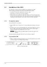
4. To ensure that the ACU is grounded – also if the ADU cable is disconnected from the
ACU, connect an extra ground wire from the rack to the ground stud on the ACU. This
ground wire must be a heavy wire or braid cable with a larger diameter than the coax
cable.
Important
Make sure that the ventilation grills at the sides of the unit are not
blocked.
Figure 2-24: Ground stud, ACU
Summary of Contents for FV-110GX
Page 1: ...GX TERMINAL FV 110GX OPERATOR S MANUAL www furuno com Model ...
Page 16: ...xiv This page is intentionally left blank ...
Page 46: ...Installation of the ADU 2 22 N connector interface on the ADU ...
Page 54: ...To connect the ADU ACU and GMU 2 30 This page is intentionally left blank ...
Page 110: ...Installation check list Functional test in harbor 6 4 This page is intentionally left blank ...
Page 164: ...Supported commands C 10 This page is intentionally left blank ...
Page 165: ...D 1 Appendix D Approvals D This appendix lists the approvals for FV 110GX OEM declaration ...
Page 166: ...OEM declaration D 2 D 1 OEM declaration ...
Page 173: ...OD 1 30 Jul 2018 H MAKI ...
Page 174: ...OD 2 30 Jul 2018 H MAKI ...
Page 175: ...OD 3 2 Oct 2018 H MAKI ...
Page 176: ...OD 4 2 Oct 2018 H MAKI ...
Page 178: ......
Page 186: ......

