Calibration
:
5-7
5.3
Calibration
Before the FV-110GX can be used you must make an azimuth and cable calibration. The
azimuth calibration is required in order to determine the offset of the ADU zero direction
to the bow-to-stern line of the ship. This procedure is fully automatic. The satellite data
for calibration can be entered directly on the calibration page or you can define a Service
profile to be used for the azimuth calibration. A cable calibration is required in order to
record the cable characteristics of the antenna cable which is used in the FV-110GX fixed
gain feature. See
Fixed TX IF principle
on page 5-14 for more information.
After the calibration you can set up blocking zones for the specific installation.
The following sections describe the steps for a successful calibration:
1.
Service profile for calibration
2.
Azimuth calibration
3.
Cable calibration
4.
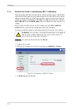
Manual One Touch Commissioning (BUC calibration)
5.3.1
Azimuth calibration
Azimuth calibration is done toward a satellite of a known position. After finding the
satellite, the system can calculate the azimuth offset of the ADU installation. The satellite
and transponder properties for the calibration can be selected from a list of service profiles
or supplied manually.
You can make an azimuth calibration in the following ways:
•
Azimuth calibration (user controlled)
•
Automatic azimuth calibration with an active satellite profile
•
Azimuth calibration with a service profile
Azimuth calibration (user controlled)
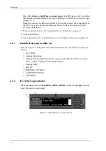
1. On the page
SERVICE > Calibration
, in the section
Azimuth calibration (user
controlled)
, select
User defined
in the
Satellite
drop down list.
Important
Make sure that the GMU is switched off at this point. Switch on the GMU
after the cable calibration.
Note
If you do not want to enter the satellite data on the calibration page you can
select a dedicated satellite service profile for calibration and select it. For
information how to set up a service profile see 5.3.2.
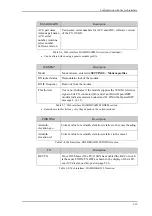
Check that the satellite transponder is visible from the location of the
installation and that it is at an elevation angle between 5 and 70 degrees.
Summary of Contents for FV-110GX
Page 1: ...GX TERMINAL FV 110GX OPERATOR S MANUAL www furuno com Model ...
Page 16: ...xiv This page is intentionally left blank ...
Page 46: ...Installation of the ADU 2 22 N connector interface on the ADU ...
Page 54: ...To connect the ADU ACU and GMU 2 30 This page is intentionally left blank ...
Page 110: ...Installation check list Functional test in harbor 6 4 This page is intentionally left blank ...
Page 164: ...Supported commands C 10 This page is intentionally left blank ...
Page 165: ...D 1 Appendix D Approvals D This appendix lists the approvals for FV 110GX OEM declaration ...
Page 166: ...OEM declaration D 2 D 1 OEM declaration ...
Page 173: ...OD 1 30 Jul 2018 H MAKI ...
Page 174: ...OD 2 30 Jul 2018 H MAKI ...
Page 175: ...OD 3 2 Oct 2018 H MAKI ...
Page 176: ...OD 4 2 Oct 2018 H MAKI ...
Page 178: ......
Page 186: ......

