background image

FURUNO


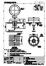
GP-330B


SP - 1 

J4452S01E 

130125


GPS 受信機  GP-330B  仕様 


1.総合 

(1) 受信周波数 

1575.42 MHz 

(2) 受信コード 

C/A コード、WAAS 

(3) チャンネル数 

GPS: 65 チャンネル、12 衛星追尾、パラレル 


WAAS: 1 チャンネル 

(4) 測位精度 

GPS: 10 m 以下(2drms) 


WAAS: 3 m 以下(2drms) 

(5) 初期捕捉時間 

約 60 秒(コールドスタート時) 

(6) 追尾速度 

999 kn 

(7) 測位更新周期 

1 秒(標準)、0.1秒(最小) 


2.インターフェイス 

(1) データの種類 

CAN bus または NMEA0183 Ver.3.1(ケーブル選択) 

(2) データセンテンス(NMEA0183) 

出力 

DTM, GGA, GLL, GSA, GSV, RMC, VTG, ZDA 

(3) CAN bus PGN(NMEA2000) 

入力 

059904, 060928, 126208/720 

出力 

059392, 060928, 065281/285/287,126208/464/720/992/996/998 


127258, 129025/026/029/033/044/538/539/540, 130822/823/944 


3.電源 


DC 12 V: 90 mA 以下 


4.環境条件 

(1) 使用温度範囲 

-25℃ ~+55℃ 

(2) 相対湿度 

95%以下(+40℃) 

(3) 保護等級 

IP56 

(4) 振動 

IEC60945 Ed.4 


5.ユニットカラー 


N9.5 

Summary of Contents for GP-330B

Page 1: ...GP 330B www furuno com 取 扱 説 明 書 GPS RECEIVER GPS受信機 OPERATOR S MANUAL Model Part no 17 468 01 rev 05 ...

Page 2: ......

Page 3: ...or service marks of their re spective holders How to discard this product Discard this product according to local regulations for the disposal of industrial waste For disposal in the USA see the homepage of the Electronics Industries Alliance http www eiae org for the correct method of disposal How to discard a used battery Some FURUNO products have a battery ies To see if your product has a batte...

Page 4: ...standard and steering compasses is 0 30 m Observe this distance to prevent inteference to a magnetic compass Do not use high pressure cleaners to clean this equipment This equipment has the waterproof rating outlined in the specifications at the back of this manual However the use of high pressure cleaning equipment can cause water ingress resulting in damage to or failure of the equipment Do not ...

Page 5: ...4 1 Pole Rail Pipe Mount 3 1 4 2 Deck Mount 4 1 4 3 Flush Mount 5 2 WIRING SETTINGS 6 2 1 CAN bus Connection Type A or N 6 2 1 1 Direct Connection 6 2 1 2 Network Connection 7 2 1 3 Routing and Connecting the Cable Assembly 8 2 2 NMEA 0183 Connection Type B or N 9 2 3 Settings for NavNet vx2 10 3 MAINTENANCE TROUBLESHOOTING 11 3 1 Maintenance 11 3 2 Troubleshooting 11 4 TECHNICAL INFORMATION 12 4 ...

Page 6: ...Please carefully read and follow the recommended procedures for installa tion and maintenance Thank you for considering and purchasing FURUNO equipment Feature The GP 330B is a high performance GPS Receiver designed for any type of vessel This compact and cost effective receiver offers extremely accurate position fixes within 3 meters with the WAAS mode activated 65 channels for receiving 12 satel...

Page 7: ...CAN bus CP20 03200 NMEA0183 CP20 03220 CP20 03220 Remote Display Unit NavNet vx2 Series AIS Autopilot Current Indicator ECDIS Radar Scanning Sonar Video Plotter Junction box or 22 910 03 22 910 03 NMEA0183 Remote Display Unit NavNet vx2 Series AIS Autopilot Current Indicator ECDIS Radar Scanning Sonar Video Plotter Junction box or ...

Page 8: ...straight MJ7P P MJ7P J for NMEA 0183 Flush Mount Kit GP 330B FLUSH KIT 001 037 630 1 Deck Mount Kit GP 330B DECK KIT 001 037 640 1 Pipe Mount Kit GP 330B PIPE KIT 001 041 560 1 Mounting hardware with standard 1 14 UNS Pole Rail Mount installation threads Safety goggles Dust mask Screwdrivers Pole Rail Mount or Deck Mount installation Teflon pipe thread tape 1 2 wide some installations Pencil some ...

Page 9: ...reasonably level with the earth s surface not tilted to one side Do not mount on top of a sailboat mast The sway will cause jitter in the data Do not mount where the GPS receiver could be a tripping hazard or tread upon Be sure there is access to the underside of the mounting surface Be sure the cable s can be routed to reduce electrical interference from other electrical wiring and any equipment ...

Page 10: ...he nut assembly captive nut and adaptor onto the cable at the 9 pin GPS connector end Do not connect the GPS receiver at this time 1 Center exit Pass the instrument connector end of the cable down through the center of the pole Be sure to leave several inches of cable extending beyond the nut assembly 2 Side exit Place the cable side exit adaptor part D over the cable Being sure the cable is passi...

Page 11: ...n the figure above coat the surface bracket part E with silicone seal ant 6 Apply silicone sealant to the three 10 x 1 2 self tapping screws to seal the deck With the pencil mark facing forward fasten the surface bracket in place Do not block the drain slots They will allow any water that accumulates inside the surface bracket to escape CAUTION Do not use a liquid thread locker as it may weaken th...

Page 12: ...cable through the center of the gasket and down through the center mounting hole in the boat 5 Plug the cable firmly into the GPS receiver 6 Orient the gasket with the arrow facing in the same direction as the alignment tab on the GPS receiver Push the gasket onto the studs and slide it over the connector Note The gasket fits one way only A groove in the gasket fits over the alignment tab on the c...

Page 13: ... activate the termination resistor See page 8 for location of 5 socket Route the cable assembly to the CAN bus device Coil any excess cable and secure it with a cable tie to prevent damage Connect the cable assembly to the CAN bus device Cable Assembly 33 1209 01 6 m 33 1209 02 10 m option GP 330B Termination Resistor ON Cut plug from cable and connect wires to terminal connector Radar Sensor FI 5...

Page 14: ... or equivalent Backbone cable connection Use this connection method to connect the GP 330B at the final node in the backbone cable Use T type connectors to connect equipment to the backbone cable Backbone cable Terminator 1 T connector T connector NavNet 3D Series FI 50 Instrument Cable Assembly 33 1209 01 6 m Power 12 VDC T connector Power 12 V GP 330B Termination Resistor OFF Terminator 2 GP 330...

Page 15: ...cket of the GPS Receiver connector to activate the termination resistor 2 1 3 Routing and Connecting the Cable Assembly Route the cable assembly to the CAN bus device Coil any excess cable and secure it with a cable tie to prevent damage Connect the cable assembly to the CAN bus device Contact pin inserted in 5 socket Tab ...

Page 16: ...o the display Coil any excess cable and secure it with a cable tie to prevent damage Connect the GPS Receiver to your NMEA 0183 display NAVnet vx2 Series Waterproof connectors by wrapping them with vulcanizing tape and then vinyl tape Bind tape ends with suitable cable ties GP 330B Female NMEA 0183 Cable Assembly 22 910 03 10 m Standard supply for Type B Optional supply for Type N Remote Display U...

Page 17: ...s in view COLD START Clear the Almanac currently stored in the GPS receiver to receive the latest Almanac WAAS SETUP menu WAAS MODE Select ON to use the WAAS mode WAAS SEARCH Set WAAS satellite search method to automatic CORRECTIONS DATA Select the type of message for WAAS connection 00 for North America 02 elsewhere WAAS settings effective from the version numbers shown below C MAP specification ...

Page 18: ...of the sky Is there interference from other antennas or instruments Is cabling damaged Is the cable run free of kinks or damage Is there damage to the GPS receiver Is there ice on the GPS receiver CAUTION CAUTION Do not disassemble the unit Disassembling the unit will damage the waterproof seal Further there are no user serviceable parts inside Do not immerse in water or pressure wash Doing so may...

Page 19: ...e to PFEC pireq PAMTC BAUD Change the baud rate from the nominal 4800 baud to 38400 baud PAMTC EN Enable disable transmission of specific sentences and change their rate of transmission PAMTC ERST Reset the user portion of nonvolatile EEPROM to factory defaults PAMTC OPTION WAAS ON OFF Set 3d Auto mode PAMTC POST Set Query Power On Self Test function PAMTC QPS Query part number and serial number v...

Page 20: ...26720 Addressable Multi Frame Proprietary PGN 126992 System Time PGN 126996 Product Information PGN 126998 Configuration Information PGN 127258 Magnetic Variation PGN 129025 Position Rapid Update PGN 129026 COG SOG Rapid Update PGN 129029 GNSS Position Data PGN 129033 Time Date PGN 129044 Datum PGN 129538 GNSS Control Status PGN 129539 GNSS DOPs PGN 129540 GNSS Sats in View PGN 059904 ISO Request ...

Page 21: ...pdate interval 1 s standard 0 1 s minimum 2 INTERFACE 2 1 Type of data CAN bus or NMEA0183 Ver 3 1 selected by cable 2 2 Data sentences NMEA0183 Output DTM GGA GLL GSA GSV RMC VTG ZDA 2 3 CAN bus PGN NMEA2000 Input 059904 060928 126208 720 Output 059392 060928 065281 285 287 126208 464 720 992 996 998 127258 129025 026 029 033 044 538 539 540 130822 823 944 3 POWER SUPPLY 12 VDC 90 mA max 4 ENVIRO...

Page 22: ......

Page 23: ...表示される内容は システムの設定や動作状態によって異なります したがって 本 書内に掲載してあるイラストは画面の表示と異なる場合があります お客様が本書の内容に従わずに本機または本ソフトウェアを取り扱われたり または当社お よび当社指定の者以外の第三者により改造 変更されることに起因して生じる障害等につい ては 当社は責任を負いかねますのでご了承ください お買い上げの機器を廃棄するときは 産業廃棄物として地方自治体の条例または規則に従っ て処理してください 詳しくは 各地方自治体に問い合わせてください 本マニュアルに記載されている社名 製品名は 一般に各開発メーカーの登録商標または商 標です 䉲䊥䉝䊦 ภ ...

Page 24: ...䜢 䛩䜛䛣䛸䚹 つᐃእ䛾䜒䛾䜢 䛳䛯ሙྜ䚸ᨾ㞀䛾ཎ ᅉ䛻䛺䜚䜎䛩䚹 㟁 䛿㻰㻯㻝㻞㼂䛿䜶䞁䝆䞁 㟁ụ䛸䛿 ู䛻䛩䜛䛣䛸䚹 㟁ᅽ㝆ୗ䛻䜘䜚䚸㻳㻼㻿ཷಙᶵ䛜ṇ䛧䛟 సື䛧䜎䛫䜣䚹 㻌 ഛ䛾䛸䛝䛿䚸Ᏻ 䜑䛜䛽䛸㜵ሻ䝬䝇 䜽䜢 䛩䜛䛣䛸䚹 䜿䜺䛾ཎᅉ䛻䛺䜚䜎䛩䚹 ḟ䛾䝁䞁䝟䝇Ᏻ 㞳䜢 ಖ䛧䛶䛟䛰䛥 䛔䚹 䝁䞁䝟䝇Ᏻ 㞳䜢 ಖ䛧䛺䛔䛸䚸Ᏻ 䛺 䛜䛷䛝䛺䛔ሙྜ䛜䛒䜚䜎䛩䚹 ᮏᶵ༢ 䛷 ᾏ䛧䛺䛔䛣䛸䚹 Ᏻ 䛻 ᾏ䛩䜛䛯䜑䚸 䛾 䛛䜙䛾 ሗ䜒 ㄆ䛧䛶䛟䛰䛥䛔䚹 䛂ὀពႏ 䛃䛾ෆᐜ 䛂 Ṇ䛃䛾ෆᐜ 䛂ᙉไ䛃䛾ෆᐜ ᶆ 䝁䞁䝟䝇 䝁䞁䝟䝇 㻜㻚㻟㼙 㻜㻚㻟㼙 ὀ㻌ព 㕲䛾㔠ᒓ䜔䚸 ຊ䜢ᣢ䛴䜒䛾䛾䛭䜀䛻 䛵䛡䛺䛔䛣䛸䚹 ሙ䛻䜘䜚䚸᪉ 䛜ṇ䛧䛟సື䛧䛺 䛔ྍ ᛶ䛜䛒䜚䜎䛩䚹 ഛ 䛻䛿㻜㻚㻡㻭䛾㐃 䝠䝳䞊䝈䚸䜎 䛯䛿䝤䝺䞊䜹䞊䜢 ព䛩䜛䛣䛸䚹 㻳㻼㻿䛻䜘䜛 㻛 ᗘ ሗ䛿䚸䜰䝯䝸䜹 ྜ ᅜᅜ㜵 䛻䛶 䛥䜜䛶䛔䜎䛩䚹 ...

Page 25: ...1 4 2 デッキマウント 4 1 4 3 フラッシュマウント 5 2 章 結線 6 2 1 CAN bus との接続 A 仕様 N 仕様 6 2 1 1 単独接続 6 2 1 2 ネットワーク接続 7 2 2 NMEA0183 との接続 B 仕様 N 仕様 8 2 3 NavNet との接続 8 3 章 保守点検 9 3 1 ふだんの保守点検 9 3 2 故障かなと思ったら 9 4 章 入出力センテンス PGN 10 4 1 NMEA0183 センテンス 10 4 2 NMEA2000 PGN 11 仕様 SP 1 パッキングリスト A 1 外寸図 D 1 相互結線図 S 1 ...

Page 26: ...ます 本機は 厳しい品質管理のもとで設計 製造さ れていますので 性能 耐久性ともに安心してご使用いただけます この取扱説明書をよくお 読みいただき 本来の性能を十分発揮させていただきますようお願い申し上げます 特徴 GP 330B は様々な船に対応できる高性能な GPS 受信機です 本機は WAAS システムを利用す ると 3 メートル以内の誤差で本船の位置を測位できます 本機の主な特徴は次のとおりです 同時に最大 12 個の衛星を追尾可能 CAN bus や NMEA0183 形式で測位データを出力可能 測定開始から約 60 秒以内に船位確定 NavNet 3D 1 の測位センサーとして最適 1 古野電気株式会社の登録商標 ...

Page 27: ...㼢㻺㼑㼠㻌㻟㻰䝅䝸䞊䝈 㻲㻵㻙㻡㻜䝅䝸䞊䝈 㻯㻼㻞㻜㻙㻜㻟㻞㻜㻜 㻺㻹㻱㻭㻜㻝㻤㻟 䝸䝰䞊䝖䝕䜱䝇䝥䝺䜲 㻺㼍㼢㻺㼑㼠 ື ู 䜸䞊䝖䝟䜲䝻䝑䝖 ὶィ 㟁Ꮚᾏᅗ䝅䝇䝔䝮㻔㻱㻯㻰㻵㻿㻕 䝺䞊䝎䞊 䝇䜻䝱䝙䞁䜾䝋䝘䞊 䝡䝕䜸䝥䝻䝑䝍 㻯㻼㻞㻜㻙㻜㻟㻞㻞㻜 㻯㻼㻞㻜㻙㻜㻟㻞㻞㻜 ᥋ 䜎䛯䛿 㻞㻞㻙㻥㻝㻜㻙㻜㻟 㻞㻞㻙㻥㻝㻜㻙㻜㻟 㻺㻹㻱㻭㻜㻝㻤㻟 䝸䝰䞊䝖䝕䜱䝇䝥䝺䜲 㻺㼍㼢㻺㼑㼠 ື ู 䜸䞊䝖䝟䜲䝻䝑䝖 ὶィ 㟁Ꮚᾏᅗ䝅䝇䝔䝮㻔㻱㻯㻰㻵㻿㻕 䝺䞊䝎䞊 䝇䜻䝱䝙䞁䜾䝋䝘䞊 䝡䝕䜸䝥䝻䝑䝍 ᥋ 䜎䛯䛿 ...

Page 28: ...工事材料 CP20 03200 000 012 581 1 CAN bus 6m ケーブル付き A 仕様 CP20 03210 000 012 582 ケーブルなし N 仕様 CP20 03220 000 037 142 NMEA0183 用 ケーブル長 10m B 仕様 オプション ケーブル組品 33 1209 01 001 193 460 10 1 CAN bus 用 6m ケーブル組品 33 1209 02 001 193 470 10 1 CAN bus 用 10m ケーブル組品 22 910 03 001 163 140 10 1 NMEA0183 用 10m ケーブル組品 MJ A7SPF SRMD 100 000 144 534 11 1 NMEA0183 用 MJ7P P MJ7P J ストレート 10m フラッシュマウ ントキット GP 330B FLUSH KIT 00...

Page 29: ... 十分に高いところを選ぶ フラッシュマウント デッキマウント 取付面水平 パイプマウント パイプが垂直 ヨットの場合 マストの頂上に取り付けない 揺れで正確な位置測定ができなくなる恐れがあります 踏んだりつまずいたりするような恐れのあるところに取り付けない 本機の底面部も点検できるようなスペースを確保する 他の電子機器や 高電圧機器からの干渉を出来るだけ受けないような位置を選ぶ たとえば レーダーや無線機 エンジン 発電機などからは少なくとも 1m は離してくださ い 䊦䊷䊒䉝䊮䊁䊅 䉟䊮䊙䊦䉰䉾䊃䊎䊷䊛䈮 䉌䈭䈇䈖䈫 䉟䊮䊙䊦䉰䉾䊃 䉝䊮䊁䊅 ㅍା䊖䉟䉾䊒 䉝䊮䊁䊅 㩿㪤㪝㪆㪟㪝㪀 㪭㪟㪝䉝䊮䊁䊅䇮 䈅䉎䈇䈲ฃା䊖䉟䉾䊒 䉝䊮䊁䊅㩿㪤㪝㪆㪟㪝㪀 䊧䊷䉻䊷䊎䊷䊛䈮 䉌䈭䈇䈖䈫 㪞㪧㪪ฃାᯏ ᦨዊ㪊㫄 ᦨዊ㪈㫄 ᦨዊ㪋㫄 ᦨዊ㪈㫄 ᦨዊ㪌㫄 ᦨዊ㪌㫄 ᦨዊ㪋㫄 ᦨዊ㪈㪅㪌㫄 䊧䊷䉻䊷 䉝䊮䊁...

Page 30: ...Nm です 4 ケーブルをパイプの中心から出すか 横 溝 から出すかを決め ケーブルの 5 ピン コネクタ側をナット組品 ナットとアダプタ の上から通します このときはまだ GPS 受信機を接続しません 1 中心から出す場合 パイプにケーブルのコネクタを通します このとき ナット組品 より約 10cm 長くケーブルを出してください 2 横 溝 から出す場合 ケーブルはアダプタ D 部 の溝を通し ナット組品はアダ プタ D 部 の上に取り付けます 必ず手で取り付け あまりきつく締めないでくだ さい 注 1 支給のアダプタを使用してください 縁がなめらかなので ケーブルを傷つけま せん 注 2 ネジロック剤を使用する場合は テフロンパイプ用ネジテープを使用してくださ い 液状のネジロック剤は使用しないでください プラスチックを弱め ふくら んでひびが入る恐れがあります 5 パイプにアダプタ ...

Page 31: ...ッピ ンネジ 3 本 とケーブルを通す穴の位置を印します 6 3mm の錐を使って下穴を 3ヵ所 および 25mm の錐を使ってケーブル穴を 1ヵ所開け ます グラスファイバーの場合 ゲルコートがしみこむまで 逆側からドリルで穴を開け 表面 のひびを最小限におさえます 7 上の図を参考に ブラケット E 部 にシリコン剤を塗ります 8 3 本の トラスタッピンネジ にシリコン剤を塗ります 9 鉛筆で付けた印が船首方向になるようにして 所定の場所にブラケットを固定します 水抜き溝をふさがないでください ブラケット内に水がたまるのを防ぐためのものです 注 液体のシリコン剤は使用しないでください プラスチックを弱め ふくらんでひびが 入る恐れがあります 10 ハウジングのネジの周りにパイプ用ネジテープを 2 回巻き付けます 11 コネクタにシリコン剤を塗ります 12 ケーブルの 5 ピンコネクタ...

Page 32: ...てロッド取付け穴を 2ヵ所 および 38mm の錐を使ってケーブル穴を 1ヵ所開けます グラスファイバーの場合 ゲルコートがしみこむまで 逆側からドリルで穴を開け 表面 のひびを最小限におさえます 5 ケーブルの 5 ピンコネクタ側をパッキンの上から通し 船体に開けたケーブル穴に通 します 6 GPS 受信機にケーブルを差し込みます 7 パッキンの矢印を船首マークと同じ方向に向けてパッキンをロッドにはめ込み コネ クタを固定します 注 パッキンは一方向にしか入りません パッキンの溝が船首マークに合うようにはめ込 んでください 8 GPS 受信機の船首マークを前方にして ロッドを船体の取付け面にはめ込みます 9 取付け面の下側から平座金 2 個 バネ座金 2 個 ナット 2 個 を使って ロッ ドを固定します ナットは必ず手で回し 締めすぎないように注意してください 10 GPS 受信機と取...

Page 33: ...位で CAN bus ネットワークの設計に重要なものです 2 1 1 単独接続 本機を CAN bus フォーマット機器と直接接続します このとき終端抵抗をオンにします ケー ブルが長すぎる場合は ループに巻いて結束バンドでしばっておきます 本機の終端抵抗 コネクタの 5 番ソケットにコンタクトピン 工事材料 を差し込むと 本機の終端抵抗がオン になります 㪞㪧㪄㪊㪊㪇㪙 ᛶ 䋺䉥䊮 䉬䊷䊑䊦 ຠ 㪊㪊㪄㪈㪉㪇㪐㪄㪇㪈䋨㪍㫄䋩 㪊㪊㪄㪈㪉㪇㪐㪄㪇㪉䋨㪈㪇㫄䇮䉥䊒䉲䊢䊮䋩 㪁䋺䉬䊷䊑䊦䈎䉌䊒䊤䉫䉕ಾᢿ䈚䇮 䉕 䇭㩷 ሶบ䉁䈢䈲䉮䊈䉪䉺䈮ធ 䈜䉎 㪄㩷䊧䊷䉻䊷䉶䊮䉰䊷㪁 㪄㩷㪝㪠㪄㪌㪇䉲䊥䊷䉵 䉮䊮䉺䉪䊃䊏䊮䉕㪌 䉸䉬䉾䊃䈮Ꮕ䈚ㄟ䉃 ...

Page 34: ... クでは 2 つの終端器を取り付けてください 3 つ以上取り付けると性能が低下します 本機の 終端抵抗はオフのままにします 基幹ケーブルの端に接続 基幹ケーブルの端のノードの T 型コネクタに GP 330B を接続する場合は 本機の終端抵抗をオ ンにします ၮᐙ䉬䊷䊑䊦 㔚Ḯ㪛㪚㪈㪉㪭 㪞㪧㪄㪊㪊㪇㪙 ᛶ 䋺䉥䊐 㔚Ḯ 㪛㪚㪈㪉㪭 㪄㩷㪥㪸㫍㪥㪼㫋㩷㪊㪛䉲䊥䊷䉵 㪄㩷㪝㪠㪄㪌㪇 䉬䊷䊑䊦 ຠ 㪊㪊㪄㪈㪉㪇㪐㪄㪇㪈䋨㪍㫄䋩 㪫ဳ䉮䊈䉪䉺 㪫ဳ䉮䊈䉪䉺 㪫ဳ䉮䊈䉪䉺 ེ㪈 ེ㪉 䊄䊨䉾䊒䉬䊷䊑䊦 ၮᐙ䉬䊷䊑䊦䋨ᦨᄢ㪉㪌㫄䋩 㔚Ḯ 㪛㪚㪈㪉㪭 㔚Ḯ 㪛㪚㪈㪉㪭 㪫ဳ䉮䊈䉪䉺 㪫ဳ䉮䊈䉪䉺 㪫ဳ䉮䊈䉪䉺 㪞㪧㪄㪊㪊㪇㪙 ᛶ 䋺䉥䊮 㪄㩷㪥㪸㫍㪥㪼㫋㩷㪊㪛䉲䊥䊷䉵 㪄㩷㪝㪠㪄㪌㪇 䉬䊷䊑䊦 ຠ 㪊㪊㪄㪈㪉㪇㪐㪄㪇㪈䋨㪍㫄䋩 㪊㪊㪄㪈㪉㪇㪐㪄㪇㪉䋨㪈㪇㫄䇮䉥䊒䉲䊢䊮䋩 䊄䊨䉾䊒䉬䊷䊑䊦 ...

Page 35: ...法装置設定メニュー 外部航法装置選択 を 古野 GPS センサー または 全て に設定します GPS センサー設定メニュー 測地系 チャートの種類を選択します WGS 84 が GPS の標準です 測位モード 2D 3D に設定します 2D 3D 2 次元測位 3 個の衛星 あるいは 3 次元測 位 4 個の衛星 GPS コールドスタート 現在持っているアルマナックデータを消去してから測位を開始しま す WAAS 設定メニュー WAAS 受信 WAAS 測位を行うときは する を選択します WAAS 衛星選択 WAAS 衛星の選択方法を 自動 に設定します 㻳㻼㻙㻟㻟㻜㻮 㻺㻹㻱㻭㻜㻝㻤㻟䜿䞊䝤䝹 ရ 㻞㻞㻙㻥㻝㻜㻙㻜㻟䠄㻝㻜㼙䚸㻮 ᵝ䛷䛿ᶆ ᵓᡂ䚸㻺 ᵝ䛷䛿䜸䝥䝅䝵䞁䠅 ᘏ㛗䜿䞊䝤䝹㻔㻹㻶㻙㻭㻣㻿㻼㻲㻛㻿㻾㻹㻰㻙㻝㻜㻜䚸㻌䜸䝥䝅䝵䞁㻕 㻠ᮏ 䝸䝰䞊䝖䝕䜱䝇䝥䝺䜲 䠄㻾㻰㻙㻟㻜䠅 㻺㼍㼢㻺...

Page 36: ...に電源を供給している機器をチェックする すべての機器が確実に接続されているか GPS 受信機の周りに障害物がないか 他のアンテナや機器からの干渉はないか ケーブルが傷んでいないか GPS 受信機が傷付いていないか GPS 受信機に着氷していないか ᵈ㩷ᗧ 䈗ᵈᗧ ಽ 䊶ᡷㅧ䈲 ኻ䈚䈭䈇䈖䈫䇯 㒐 䉲䊷䊦䈏䈲䈏䉏䉎ᕟ䉏䈏䈅䉍䉁䈜䇯 䉁䈢䇮Ἣἴ䇮ᗵ㔚䇮䉬䉧䈱ේ 䈮䈭䉍䉁 䈜䇯 Ⴃᢱ䇮㒐 䇮ធὐᓳᵴ 䈭䈬䈲 ᯏ ṁ 䉕 䉖䈪䈇䉎䈱䈪䇮ᯏེ䈱Ⴃⵝㇱ ಽ䉇᮸ ㇱຠ䈮䈲 䈚䈭䈇䈪䈒䈣䈘䈇䇯 ᯏེ䈱Ⴃⵝㇱಽ䉇᮸ ㇱຠ䉕ഠൻ䈘䈞䉎 䈖䈫䈏䈅䉍䉁䈜䇯 䈮䇮᮸ 䈱䉮䊈䉪䉺䈮 䈜䉎䈫 䈜䉎ᕟ䉏䈏䈅䉍䉁䈜䈱䈪 ኻ 䈮 䈚䈭䈇䈪䈒䈣䈘䈇䇯 ᴚ䈘䈞䈢䉍䇮㜞 ᵞᵺ䈲䈚䈭䈇䈖䈫䇯 ᯏེౝㇱ䈱䉶䊮䉰䊷䈏 ᴚ䈮䉋䉍䇮 㓚䈱ේ 䈮䈭䉍䉁䈜䇯 ...

Page 37: ... PGN 4 1 NMEA0183 センテンス 本機で採用している NMEA0183 の出力センテンスは以下のとおりです デフォルト出力 GPDTM 測地系 GPGGA GPS の測位状況 GPGLL 緯度 経度 GPGSA GPS の DOP 値と衛星番号 GPGSV 視界内の衛星情報 GPRMC GPS 航法情報 GPVTG 進路 対地船速 GPZDA UTC 時刻 日付 PFEC pidat PFEC pireq への応答 ...

Page 38: ...答グループ機能 PGN126464 送受信 PGN リスト PGN126720 アドレス可能マルチフレーム メーカー独自 PGN126992 システム時刻 PGN126996 製品情報 PGN126998 構成情報 PGN127258 磁気偏差 PGN129025 緯度 経度 PGN129026 対地船速 進路 PGN129029 GNSS 測位位置 PGN129033 UTC 時刻 日付 PGN129044 測地系 PGN129538 GNSS 受信機パラメータ PGN129539 DOP 値 HDOP VDOP TDOP PGN129540 視界内 GNSS 衛星情報 PGN059904 要求 PGN060928 アドレス要求 PGN126208 要求グループ機能 PGN126208 命令グループ機能 PGN126720 アドレス可能マルチフレーム メーカー独自 ...

Page 39: ...6 追尾速度 999 kn 7 測位更新周期 1 秒 標準 0 1秒 最小 2 インターフェイス 1 データの種類 CAN bus または NMEA0183 Ver 3 1 ケーブル選択 2 データセンテンス NMEA0183 出力 DTM GGA GLL GSA GSV RMC VTG ZDA 3 CAN bus PGN NMEA2000 入力 059904 060928 126208 720 出力 059392 060928 065281 285 287 126208 464 720 992 996 998 127258 129025 026 029 033 044 538 539 540 130822 823 944 3 電源 DC 12 V 90 mA 以下 4 環境条件 1 使用温度範囲 25 55 2 相対湿度 95 以下 40 3 保護等級 IP56 4 振動 IEC6094...

Page 40: ...ASHER 03 312 01 000 160 546 10 2 フラッシュマウントキット FLUSH MOUNT KIT ナット THUMB NUT 20 613 01 000 168 934 10 2 3 パッキン GASKET 04 672 01 000 168 932 10 1 ロッド STUD 03 282 01 000 168 933 10 2 3 デッキマウント DECK MOUNT KIT トラスタッピンネジ SELF TAPPING SCREW 10X1 2 000 168 931 10 3 ブラケット SURFACE BRACKET 04 691 03 000 168 930 11 1 1 工事材料 INSTALLATION MATERIALS ケーブル クミヒン NMEA2000 CABLE ASSEMBLY 33 1209 01 6M 001 193 ...

Page 41: ...14 01 000 160 545 10 2 平座金 FLAT WASHER 03 312 01 000 160 546 10 2 フラッシュマウントキット FLUSH MOUNT KIT パッキン GASKET 04 672 01 000 168 932 10 1 ロッド STUD 03 282 01 000 168 933 10 2 3 ナット THUMB NUT 20 613 01 000 168 934 10 2 3 デッキマウント DECK MOUNT KIT トラスタッピンネジ SELF TAPPING SCREW 10X1 2 000 168 931 10 3 ブラケット SURFACE BRACKET 04 691 03 000 168 930 11 1 1 工事材料 INSTALLATION MATERIALS コンタクトピン CONTACT PIN 05 ...

Page 42: ...A 3 ...

Page 43: ... CT 4 UWOK D 1 ...

Page 44: ... CT 4 UWOK D 2 ...

Page 45: ... CT 4 UWOK D 3 ...

Page 46: ...S 1 ...

Page 47: ...icient Otherwise the invoice with serial number name and stamp of the dealer and date of purchase is shown For the Onboard Warranty your FURUNO certified dealer will take care of all registrations 5 Warranty Claims For the Standard Warranty simply send the defective product together with the invoice to a FURUNO national distributor For the Onboard Warranty contact a FURUNO national distributor or ...

Page 48: ...c or its authorized dealer at the time of request for warranty service This warranty is valid for installation of products manufactured by Furuno Electric Co hereafter FURUNO Any purchases from brick and mortar or web based resellers that are imported into other countries by anyone other than a FURUNO certified dealer agent or subsidiary may not comply with local standards FURUNO strongly recommen...

Page 49: ...ella dichiarazione di conformità UE è disponibile al seguente indirizzo Internet Ar šo Furuno Electric Co Ltd deklarē ka augstāk minēts radioiekārta atbilst Direktīvai 2014 53 ES GP 330B ELi vastavusdeklaratsiooni täielik tekst on kättesaadav järgmisel internetiaadressil С настоящото Furuno Electric Co Ltd декларира че гореспоменат тип радиосъоръжение е в съответствие с Директива 2014 53 ЕС Цялост...

Page 50: ... o skladnosti je na voljo na naslednjem spletnem naslovu O texto integral da declaração de conformidade está disponível no seguinte endereço de Internet Aš Furuno Electric Co Ltd patvirtinu kad pirmiau minėta radijo įrenginių tipas atitinka Direktyvą 2014 53 ES Visas ES atitikties deklaracijos tekstas prieinamas šiuo interneto adresu Furuno Electric Co Ltd igazolja hogy fent említett típusú rádiób...

Page 51: ......

Page 52: ... No OMC 44520 E Printed in Japan 機器の修理 使用方法等に関するお問い合わせは お買い上げの販売店 代理店 最寄りの 当社支店 営業所あてへお願いします Elemental Chlorine Free The paper used in this manual is elemental chlorine free FURUNO Authorized Distributor Dealer お問い合わせは MAY 2008 MAY 15 2019 A E 00016889615 ...

Reviews: