4
4.
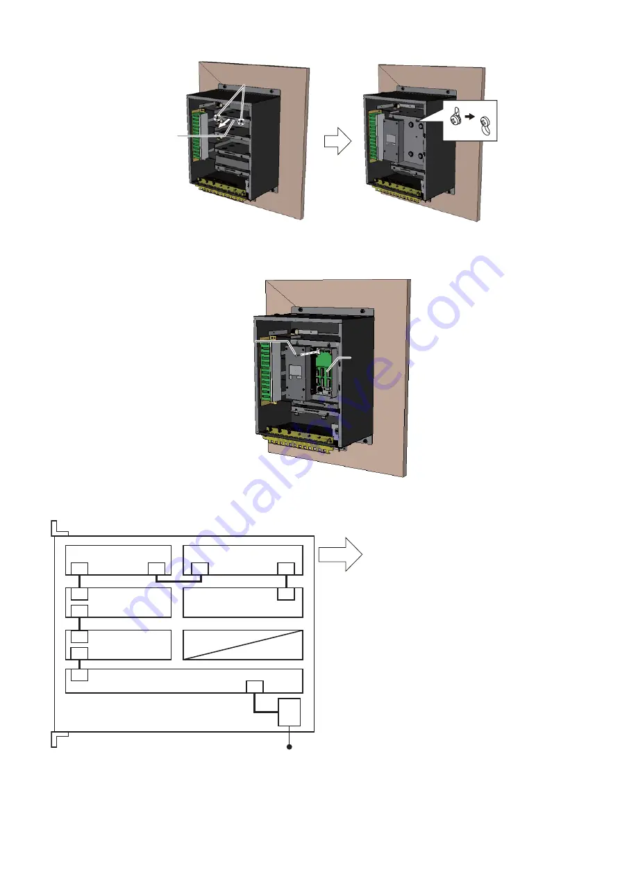
Hang the plate to the screws loosened at step 3.
The figure below is an example for the first additional unit.
5.
Unfasten four binding screws (M4×10) to remove the additional sensor adapter cover.
6.
Fix the unit to the fixing plate with four binding screws (M4×10, supplied with sensor adapter).
7.
Connect the optional cable assy. (AI.14-8AI.34-6L1000) between sensor adapters.
The internal wiring between sensor adapters in the junction box is as shown in the figure below.
8.
See “8. Wiring for MC-3000S-N” (page 7) and “9. Wiring for MC-3020D-N and MC-3010A-N” (page 9) to connect
the cable from the external equipment to the sensor adapter.
9.
See “5-2. Setting the Termination Resistor and Modbus Address” (page 5) to set the termination resistor and
Modbus address.
Fixing plate
Fixing plate
Unfasten these binding screws
to pull out the fixing plate.
Unfasten these binding screws
to pull out the fixing plate.
Binding screw
(4 pcs)
Binding screw
(4 pcs)
Sensor adapter
(MC-3010A-N or
MC-3020D-N
䠅
Sensor adapter
(MC-3010A-N or
MC-3020D-N
䠅
J1
24 VDC
MC-3000S-N
MC-3020D-N
MC-3020D-N
MC-3020D-N
First additional unit*
Second additional unit*
J2
J1
J1
J2
J1
J2
J1
J2
J1
J2
J1
Front
*: The unit may be pre-installed and the internal
wiring completed depending on the configuration
purchased.
Summary of Contents for IF-8540
Page 12: ...17 Jul 2015 H MAKI ...


