9. INSTALLATION OF VIDEO PLOTTER KIT
57
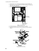
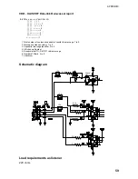
6. Fasten the ground wire in the cable assy. of the M-card assy. with an M3 x
8 screw and toothed washer (M3) as shown on the previous page.
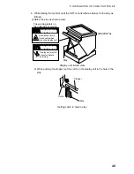
7. Unfasten four pan head screws (M4 x 8) from the display pedestal to
remove the front panel lid.
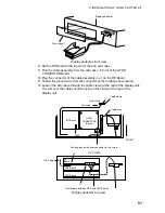
8. Set the RP Board in the top slot of the pcb card case.
9. Run the cable assembly from the M-card assy. in front of the GYRO
PROCESSOR Board.
10. Plug in the connecter of the cable assembly to J1 on the RP Board.
11. Follow steps 12 thru 21 in paragraph 9.1.

