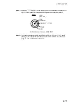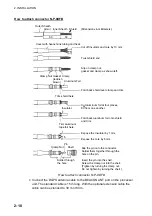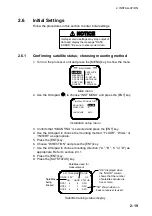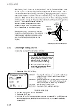
2. INSTALLATION
2-9
2.3
Installing the Processor Unit
The processor unit should be mounted aligned with the ship’s fore-and-aft line. It
can be mounted on the deck, bulkhead, or on the underside of a desk. Choose a
mounting location which allows you to easily view the power lamp on the top of
the unit and which is within
±
2.5
°
of the ship’s fore-and-aft line.
2.3.1 Deck
mount
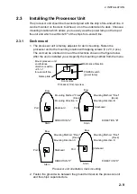
1. The processor unit is factory adjusted for deck mounting. Fasten the
processor unit to the mounting location with tapping screws (5 x 20, 4 pcs.).
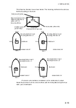
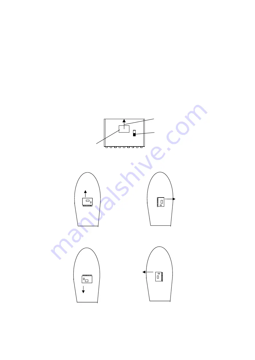
The unit can be oriented in one of the directions shown in the figure below.
After the unit is installed you will specify the mounting method from the menu.
Bow
Stern
Stern
Stern
Stern
Port
Starboard
Mounting Method: "Floor"
(Deck)
Mounting Direction: A
Mounting Method: "Floor"
(Deck)
Mounting Direction: B
Mounting Method: "Floor"
(Deck)
Mounting Direction: C
Mounting Method: "Floor"
(Deck)
Mounting Direction: D
Bow
Port
Starboard
Bow
Port
Starboard
Bow
Port
Starboard
Name plate
Connectors
Reference Direction
POWER switch
(power lamp)
Processor Unit, top view
Mount processor unit
so reference
direction is within
±
2.5
°
of
fore-and-aft line.
DIRECTION "A"
DIRECTION "B"
DIRECTION "C"
DIRECTION "D"
Processor unit orientation, deck mounting
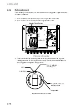
2. Fasten the ground wire between the ground terminal on the processor unit
and the ship’s superstructure.
Summary of Contents for SC-120
Page 1: ...SATELLITE COMPASS SC 120...
Page 10: ...This page is intentionally left blank...
Page 14: ...This page is intentionally left blank...
Page 58: ...This page is intentionally left blank...
Page 71: ...APPENDIX A 5 NAV OUT1 Port Output drive capability Max 10 mA HDG4 NAV2 port RS 232C level...
Page 82: ......
Page 83: ......
Page 84: ......
Page 87: ...Takahashi T Takahashi T D 1...
Page 88: ...Takahashi T Y Hatai D 2...
Page 89: ...Takahashi T Y Hatai D 3...
Page 90: ...Takahashi T Y Hatai D 4...
Page 91: ...Takahashi T Y Hatai D 5...
Page 92: ...D 6...
Page 93: ......
Page 94: ......
Page 96: ......

