2. INSTALLATION
2-13
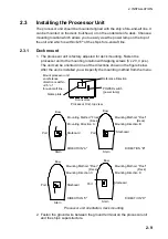
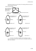
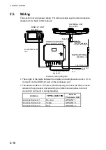
The reference direction is as shown below. The mounting method is the same as
that for mounting on the deck.
Bow
Stern
Stern
Stern
Stern
Port
Starboard
Mounting Method: Invert
Mounting Direction: A
Mounting Method: Invert
Mounting Direction: B
Mounting Method: Invert
Mounting Direction: C
Mounting Method: Invert
Mounting Direction: D
Bow
Port
Starboard
Bow
Port
Starboard
Bow
Port
Starboard
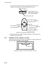
Name plate (other side)
Connectors
Reference Direction
POWER switch
(power lamp)
Processor Unit, rear view
Mount processor unit so
reference direction is
within
±
2.5
°
of
fore-and-aft line.
DIRECTION "A"
DIRECTION "B"
DIRECTION "C"
DIRECTION "D"
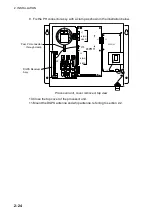
Processor unit orientation, installation on the underside of a desk
Mount the processor unit on a level surface with its name plate facing the bow,
stern, port or starboard.
Summary of Contents for SC-120
Page 1: ...SATELLITE COMPASS SC 120...
Page 10: ...This page is intentionally left blank...
Page 14: ...This page is intentionally left blank...
Page 58: ...This page is intentionally left blank...
Page 71: ...APPENDIX A 5 NAV OUT1 Port Output drive capability Max 10 mA HDG4 NAV2 port RS 232C level...
Page 82: ......
Page 83: ......
Page 84: ......
Page 87: ...Takahashi T Takahashi T D 1...
Page 88: ...Takahashi T Y Hatai D 2...
Page 89: ...Takahashi T Y Hatai D 3...
Page 90: ...Takahashi T Y Hatai D 4...
Page 91: ...Takahashi T Y Hatai D 5...
Page 92: ...D 6...
Page 93: ......
Page 94: ......
Page 96: ......

