4. MAINTENANCE, TROUBLESHOOTING
4-3
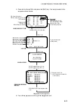
5. Press
◄
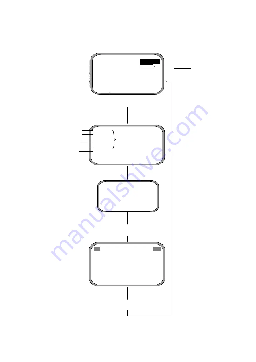
to choose YES and press the [ENT] key. The test proceeds in the
sequence shown below.
HDG OUT1 connector
HDG OUT4 connector
NAV OUT1connector
NAV OUT2 connector
BEACON EXT connector
DISPLAY connector
HDG
- -
HDG4 - -
NAV1 - -
NAV2 - -
B-EXT - -
DSP
OK
CNT= (STOP: PWR OFF)
SOFTWARE VERSION
DISPLAY
205-1312-0**
PROCESS
205-1131-0**
GPS1
205-1313-0**
GPS2
205-1313-0**
GPS3
205-1313-0**
DGPS
085-0182-0**
CNT=*** (
STOP: PWR OFF)
After 3 sec.
After 3 sec.
<LCD CHECK>
ALL ON 2 SEC.
ALL OFF 3 SEC.
All LCD segments go on 2 sec.,
All LCD segments go off 3 sec.
ROM, RAM, KEY check appears after
3 sec.
ROM
RAM
BAT
GPS1
OK
OK
PUSH KEY
GPS2
OK
OK
GPS3
OK
OK
CAL
OK
OK
OK
DISP
OK
OK
OK
DGPS
OK
OK
CNT= (STOP: PWR OFF)
Number of times test executed
GPS receiver
Processor unit
Display unit
Factory use
Internal beacon receiver
KEY TEST
Press each key one by
one. Pressed key’s name
appears here if key
is functioning properly.
To stop the test turn
off the power.
I/O TEST
ROM, RAM, KEY TEST
DISPLAY TEST
PROGRAM VERSION
DISPLAY
** = Program version no.
*** = No. of times test conducted
consecutively.
OK shown for normal;
NG (No Good) shown for error
Diagnostic test sequence
6. Turn off the processor unit to quit the diagnostic test1.
Summary of Contents for SC-120
Page 1: ...SATELLITE COMPASS SC 120...
Page 10: ...This page is intentionally left blank...
Page 14: ...This page is intentionally left blank...
Page 58: ...This page is intentionally left blank...
Page 71: ...APPENDIX A 5 NAV OUT1 Port Output drive capability Max 10 mA HDG4 NAV2 port RS 232C level...
Page 82: ......
Page 83: ......
Page 84: ......
Page 87: ...Takahashi T Takahashi T D 1...
Page 88: ...Takahashi T Y Hatai D 2...
Page 89: ...Takahashi T Y Hatai D 3...
Page 90: ...Takahashi T Y Hatai D 4...
Page 91: ...Takahashi T Y Hatai D 5...
Page 92: ...D 6...
Page 93: ......
Page 94: ......
Page 96: ......

