background image


IN-1


INDEX 

B


Battery installation (catch sensor)................ 44 
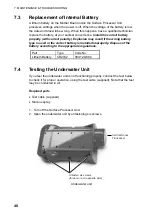
Battery replacement .................................... 48 

C


Catch sensor 

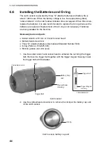
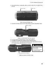
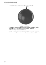
battery installation.................................... 44 
catch sensor dialog box ........................... 41 
description .................................................5 
LED sequence ......................................... 43 
O-ring replacement .................................. 44 
testing for switch activation...................... 43 
transmission frequency............................ 43 

Clear screen ................................................36 
Color indicator ............................................. 36 
Color threshold ............................................ 38 
Colors 

echosounder............................................ 30 
lines, symbols .......................................... 19 
sonar........................................................ 21 

COM port ..................................................... 37 
Communication menu.................................. 37 
Configuration data ....................................... 26 

D


Data gain 

echo sounder........................................... 28 
sonar........................................................ 15 

Depth/Temperature display 

scale text size .......................................... 33 
temp/depth limits...................................... 32 
temp/depth offset ..................................... 32 
unit of temperature .................................. 31 

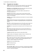
Diagnostic test ............................................. 51 
Draw toolbar ..................................................7 

E


Echo sounder 

beamforming............................................ 38 
data gain.................................................. 28 
drawing lines............................................ 30 
drawing symbols...................................... 30 
echo sounder settings dialog box ............ 28 
gain.......................................................... 28 
grid........................................................... 30 

noise filter.................................................23 
range........................................................28 

Echo sounder beamforming.........................38 
Echo sounder settings dialog box ................28 

F


File menu .....................................................35 
File progress bar ..........................................24 
Freezing the display 

echo sounder ...........................................28 
sonar........................................................15 

Frequency (sonar)........................................15 
Full screen ...................................................36 
Fuse replacement ........................................47 

G


Gain (echo sounder) ....................................28 
Grid 

echo sounder ...........................................30 
sonar........................................................22 

H


Help menu ...................................................39 
HOLD button ..........................................15, 28 

I


Indications......................................................9 

L


Lines 

clearing from sonar, echo sounder...........19 
drawing on echo sounder.........................30 
drawing on sonar .....................................18 

Locked mode (sonar) ...................................13 

M


Main toolbar ...................................................7 
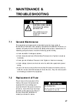
Maintenance ................................................47 
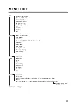
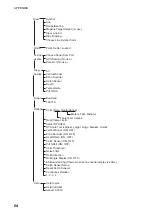
Menu tree.....................................................53 

N


Noise filter....................................................23 

O


Options menu...............................................38 
O-ring replacement (catch sensor)...............44 

Summary of Contents for TS-331A

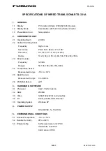
Page 1: ...WIRED TRAWL SONAR TS 331A ...

Page 2: ...8 65 2111 0798 65 2111 Fax Fax 0798 65 4200 0798 65 4200 FIRST EDITION FIRST EDITION JAN JAN 2005 2005 Printed in Japan Printed in Japan All rights reserved All rights reserved Pub No Pub No OME 13210 OME 13210 00015138400 00015138400 00015138400 00015138400 DAMI DAMI TS 331A TS 331A 0 0 0 1 5 1 3 8 4 0 0 0 0 0 1 5 1 3 8 4 0 0 OME13210A00 OME13210A00 OME13210A00 OME13210A00 O M E 1 3 2 1 0 A 0 0 O...

Page 3: ...he correct battery and install it properly to prevent explosion of the battery WARNING Do not disassemble or modify the equipment Fire electrical shock or serious injury can result Immediately turn off the power at the switchboard if water leaks into the surface processor unit Continued use of the equipment can cause fire or electrical shock Contact a FURUNO agent for service Install batteries in ...

Page 4: ...ilter 23 2 11 Recording Sonar Data 24 2 12 Playing Back Sonar Data 24 2 13 Saving Loading System Configuration 26 2 13 1 Saving system configuration 26 2 13 2 Loading system configuration 26 3 ECHO SOUNDER OPERATION 27 3 1 Echo Sounder Image 27 3 2 Adjusting the Echo Sounder Image from the Sounder Settings Dialog Box 28 3 2 1 Choosing the display range 28 3 2 2 Adjusting data gain 28 3 2 3 Adjusti...

Page 5: ...ors a 120kHz downward looking echo sounder four catch indicators and a pitch and roll indicator for monitoring the attitude of the trawl unit The trawl unit is connected to the Surface Processor Unit by a 2 conductor cable This cable provides 130 VDC power to the trawl unit as well as two way communications Some of the main features are High resolution net profile Graphic presentation of net attit...

Page 6: ...ply Surface Processor Unit Winch Power source 100 240VAC 1φ 50 60 Hz Underwater Unit Catch Sensor option 4 max Standard supply Optional supply Local user supply Cable Block UNDERWATER SECTION SHIPBOARD SECTION Mouse Keyboard System configuration ...

Page 7: ... changed in the Settings Dialog box after clicking the Pitch Roll window Remedy 1 Click Don t send in the error message box at the bottom of the screen 2 The application is quitted click the TS331A icon to start up the application To change a sonar or echo sounder setting after application error occurs first click the corresponding window or run the corresponding diagnostic and then change the set...

Page 8: ...vi This page intentionally left blank ...

Page 9: ...to control system parameters such as acoustic operating range scan speed scan area etc It also displays real time data such as depth temperature vertical sonar images echo sounder images pitch and roll and catch sensor information on the screen in resizable windows The mouse connects at the rear of the Processor and functions to control the system from various menus Note that the system can also b...

Page 10: ... from the back of the case The gray echo sounder transducer is mounted near the front of the unit The catch sensor receiver transducer is located at the back of the unit to the right of the vertical sonar transducer Pressure Sensor Echo Sounder Transducer Third Wire Cable Catch Sensor Receiver Transducer Vertical Sonar Transducer Underwater unit cover removed 1 2 2 Trawl system Underwater Unit Thi...

Page 11: ...n mid water and pelagic trawls the ground rope usually becomes positioned below the head rope and hence the ground rope is easily detected with the underwater unit on the head rope The underwater unit is typically enclosed in a pouch made of fine mesh netting and attached to the head rope with ropes The pouch is attached to a small mesh net smaller trawlers with ropes to stabilize the underwater u...

Page 12: ...er right corner of the screen or use the menu command File Exit When the power is turned on the normal screen display should appear Then the sonar head calibrates itself by moving its transducer to the center or zero angle and waits for the scan command from the Processor The head then scans based on the last used settings of MODE SECTOR TRAIN and SPEED If the message No Communication appears chec...

Page 13: ...t via the acoustical link and sent to the Processor Tx frequency for each sensor is selectable with an internal jumper block The catch sensor is powered by three D alkaline batteries If they have not been installed see page 44 for how to install them Note If the unit will not be used for a long period of time remove the batteries Acoustic transducer LED Electrode Lanyard Secured to codend of net P...

Page 14: ...mation DateTime 24 SEP 04 1 23 01 Ship s Course Ship s Speed Trawl Direction Tr Water spd CE Water spd Trawl Pitch 0 0 Roll 0 0 Cod End Pitch Roll Depth Bottom Trawl CodEnd 3 2 3 2 1 1 6 6 1 1 2 3 3 2 1 1 6 6 1 1 2 1 2 3 4 5 6 7 8 1 2 3 4 5 6 7 8 Items available depend on active window Items not available appear in gray Vertical 6M DIV File View Color Table Grids Draw Mode Communication Diagnostic...

Page 15: ... menu sub menu or choose an option click it with the left mouse button A sub menu which has an arrow means it contains an options selection window such as the Echo Sounder sub menu shown above File View Color Table Grids Draw Mode Communication Diagnostics Sonar Options Help Menu bar 1 5 2 Toolbars The main toolbar and the draw toolbar are displayed across the top of the application window below t...

Page 16: ...display gain by 1 per cent for vertical sonar and echo sounder Increases train angle by 10 degrees vertical sonar only Decreases train angle by 10 degrees vertical sonar only Increases sector size by 10 degrees vertical sonar only Decreases sector size by 10 degrees vertical sonar only Increases sonar scan speed vertical sonar only Decreases sonar scan speed vertical sonar only Clears the screen v...

Page 17: ...vailable with active window is shown in gray Active window indicator Color changes according to active window Med blue Sonar Green Depth temp Red Echo sounder Light blue Catch sensor Purple Pitch roll Catch sensor indicator Time figure is how long since sensor has been activated Color inside each section changes with catch sensor status Triggered Red Standby Yellow Sleep Bkgd color DateTime 24 SEP...

Page 18: ...al sonar window echo sounder window depth temperature window pitch roll window and catch sensor window To activate a pop up window place the cursor in the window corresponding to the pop up menu you want to use and then click the screen with the right mouse button Vertical sonar Echo sounder Depth temperature Pitch roll Catch sensor Pop up windows ...

Page 19: ...d Choose desired mode from the Mode menu 2 1 1 Polar mode This mode is used for operating the sonar to scan a 360 area The transducer location is in the middle of the sonar image display with the zero heading vertically down on the display Ground rope of trawl Fish in trawl Polar mode display Polar mode concept ...

Page 20: ...ctor combo box in the Vertical Sonar settings dialog box Sector size can be from 0 to 360 in 10 increments The user can move the mid point of the sector to any angle in 10 increments by selecting the desired train angle from the Train combo box in the vertical sonar settings dialog box The user can use the Zoom Factor command in the View menu to enlarge or shrink sonar images and the mouse can be ...

Page 21: ...s an echo sounder with the transducer locked at 0 sector size The transducer location is at the top of the sonar image display and the image data is displayed across the screen from right to left Ground rope of trawl Bottom Individual fish angular echoes in trawl Locked mode display ...

Page 22: ... not displayed click the sonar image with the left mouse button and then choose Show Sonar Settings from the View menu Vertical sonar settings dialog box 2 2 1 Choosing the display range The Range combo box lets you choose desired display range from the ranges shown in the table below Ranges Meters Feet Fathoms 250 750 125 200 600 100 150 450 75 100 300 50 80 240 40 60 180 30 50 150 25 40 120 20 3...

Page 23: ...of vertical sonar The options are 0 3 deg slow one shot covers 0 3 0 6 deg medium one shot covers 0 6 0 9 deg fast one shot covers 0 9 1 2 deg faster one shot covers 1 2 2 4 deg fastest one shot covers 2 4 2 2 6 Choosing sonar frequency Choose the vertical sonar operating frequency for high or low 2 2 7 Freezing the display Click the HOLD button to freeze the system from interrogating sensors and ...

Page 24: ... may be caught on some object Image and fishing operations The illustration and descriptions below show the relation between trawl and the LOCKED mode image in bottom trawling 1 2 3 4 5 6 7 8 9 10 11 Ground Rope Display range changed Example fishing operation and echo sounder image 1 The trawl is set into water and begins descending In the image the distance between the transducer and the bottom g...

Page 25: ... trawl is passing over the shoal The ground rope seen off the bottom indicates that the shoal has been cleared 6 The trawl has settled on the bottom again 7 The trawl is being towed along the bottom 8 Hauling of the trawl has begun 9 10 As the hauling proceeds the bottom echoes are becoming distant and the sea surface echoes are getting nearer to the transmission line 11 Hauling is completed ...

Page 26: ...ed at the cursor intersection Repeat the above procedure to draw another symbol Cursor Symbol Appearance of symbol on the display 2 4 2 Drawing a line Choose Line from the Draw menu or click the button on the draw toolbar Roll the mouse to position the cursor on the starting point and click the left mouse button Roll the mouse again to position the cursor on the end point and click the left mouse ...

Page 27: ...and then click the OK button Color dialog box 2 4 4 Clearing line symbol art Clearing all symbols Place the cursor on a symbol and then double click the left mouse button Clearing a line Place the cursor on the ending point of the line you wish to erase and then double click the left mouse button Clearing all symbol line art Choose Clear line Art from the Draw menu Stopping drawing The Stop Drawin...

Page 28: ...measure the range and bearing and click the left mouse button The range and bearing from own ship to the point is shown To find the range and bearing between to other points repeat the above procedure Range and bearing to point R 199 5m B 348 1 Deg Finding range and bearing from own ship to a point 2 6 Zoom Zoom Factor on the View menu lets you choose the zoom magnification from 100 125 150 175 20...

Page 29: ... to 118 colors ranging from black low strength through blue green orange yellow white and red highest strength Normal Low Same colors as Normal High but a lower color intensity Green 118 shades of green Grey 118 shades of grey white on black Reverse Grey 118 shades of grey black on white Brown Yellow 118 mixed shades of brown and yellow Green Blue 118 mixed shades of green and blue Green Yellow 11...

Page 30: ...rid Square grid Displays a square grid Circular grid Square grid Circular and square grids No Grid Check to turn off grid Scale options Turns scale on or off turns shadow behind scale on or off and chooses text scale text size Enable Shadow Check to enable shadowing behind scale Choose Shadow Color Click to display color dialog box to choose color of shadow Scale Text Size Choose text size from sm...

Page 31: ...its Depth Range selected 2 10 Noise Filter You may encounter occasional or intermittent noise and interference on the vertical sonar display or echo sounder display Noise is mostly caused by electrical equipment engine or propeller noise from own ship or noise from other sonars being operated nearby To suppress this noise check Noise Filter on the Options menu Uncheck it if no noise is present ...

Page 32: ...bar button When the program is running in file playback mode the frame window will show a File Playback dialog bar You can drag and dock it to a convenient place on the screen This dialog bar lets you control the playback speed and playback file position File progress indicator playback speed selector File Progress A slider bar with the pointer showing file playback position similar to the slider ...

Page 33: ...file You can once again change the operation to real time data interrogation by selecting menu File Connect to Sonar Head or clicking the Toolbar button When the system begins acquiring data from the sonar head the current data file will be closed The TS 331A program provides several convenient methods menu commands dialog boxes and toolbar commands to control the sonar unit s operations operating...

Page 34: ...may then load the settings into the system This is convenient for setting up the equipment according to fishing ground targeted fish etc To do this choose Save Configuration from the File menu Name your file and click the Save button 2 13 2 Loading system configuration Choose Load Configuration from the File menu to load a configuration file into the system Choose your file and then click the Save...

Page 35: ...ho sounder window at the right side of the screen Ground rope of trawl Fish in trawl VERTICAL SONAR IMAGE ECHO SOUNDER IMAGE Fish in trawl Ground rope of trawl Echo Sounder Range 50 M Gain 10 dB Sonar settings Range 30 M Gain 70 Speed 03 Mode Polar Freq High Vertical sonar and echo sounder images ...

Page 36: ...djusting data gain Adjust the gain from the Data Gain combo box The gain range is 0 100 Data gain is used to increase or decrease the intensity color levels of the vertical sonar and sounder images collectively 3 2 3 Adjusting echo sounder gain Choose the ES Gain combo to adjust the gain of the connected echo sounder The gain can be adjusted from 0dB to 20dB in 1 dB increments 3 2 4 Freezing the d...

Page 37: ... coverage area of the sounding beam it is displayed as a line almost parallel with the transmission line If a fish school appears between the transmission line and the ground rope it can be considered to be entering the trawl Height of Trawl Opening Fish School Ground rope of trawl Bottom Transmission line Echo sounder display ...

Page 38: ... You may display a line grid on the echo sounder display Check Line Grid on the Grids menu to display the grid 10 M 20 M 30 M 40 M 50 M Line grid 3 6 Zoom Zoom Factor on the View menu lets you choose the zoom magnification from 100 125 150 175 200 300 and 400 3 7 Colors You may choose the color arrangement for the echo sounder Open the Color Table menu and check color desired For details see page ...

Page 39: ...ure and depth Thus the number of minutes of data shown depends on many factors including operating range and which sensors are active when the timer expires Temperature yellow Depth white Temperature Depth Unit of temperature measurement Unit of depth measurement Temperature scale Depth scale Depth Temperature display 4 1 Unit of Temperature Depth Measurement You may choose the unit of temperature...

Page 40: ... click the OK button Set Depth Temperature Scales dialog box 4 3 Depth Temperature Offset If the depth and or temperature readout is incorrect you may enter an offset to correct it them Choose DT Offset from the Options menu to show the Depth Temp Offset dialog box Enter the appropriate offset with the spin buttons and then press the OK button To remove the offsets click the Reset button Depth Tem...

Page 41: ... DEPTH TEMPERATURE DISPLAY 33 4 4 Depth Temperature Scale Text Size You may choose the size of the depth temperature scale text with DT Scale Text on the Options menu Options menu DT Scale Text selected ...

Page 42: ...4 DEPTH TEMPERATURE DISPLAY 34 This page intentionally left blank ...

Page 43: ...ult serial port for communications between the analog interface board and surface control system Print Prints an image of the currently selected window Print Preview Displays the currently selected window on the screen as it would appear printed Print Setup Selects a printer and printer connection Exit Use this command to terminate your TS 331A program System will save your display layout sonar se...

Page 44: ...r Restore Image Use this command to restore the vertical sonar or echo sounder image When you move the image by clicking and dragging or zooming the image the image may not be seen in the viewing window Use this command to restore the image to its original size and position Color Indicator Use this command to display and hide the color table indicator bar which displays the color table used to rep...

Page 45: ...n port for sonar data acquisition Choose desired port from the combo box and click the OK button GPS Data In No use Data Out No use 5 4 Sonar Menu BowScan Sets TS 331A exe to Bowscan mode All sensors are disabled except vertical sonar TS 331A Sets TS 331A exe to TS 331A mode All sensors are functional ...

Page 46: ...hreshold show as red Data Value Detection Threshold Display as Black Detection Threshold Data Value Saturation Threshold Datavalue 107 Datavalue Saturation Threshold Data Value Saturation Threshold Display as Red Roll Correction Enable disable roll correction If enabled vertical sonar image display will compensate the roll offset Roll Angle Display ON Display a dashed line indicating the roll angl...

Page 47: ...lp Contents Offers you a list of contents on which you can get help Use this command to display the opening screen of Help From the opening screen you can jump to step by step instructions for using TS 331A and various types of reference information About Use this command to display the copyright notice and version number of your copy of TS 331A as well as contact information ...

Page 48: ...5 MENU DESCRIPTION 40 This page intentionally left blank ...

Page 49: ...nable disable that particular catch sensor There can be a maximum of four catch sensors installed at a time Catch Sensor ID edit boxes The Catch Sensor ID is a number used to distinguish different catch sensors Each sensor transmits an acoustic signal with its own fixed frequencies so the system knows which one is installed received a standby signal or triggered received a triggered signal TS 331A...

Page 50: ...ch counts sensor activation time If the trigger indicated by showing red in a sensor status window is present for two minutes the timer starts counting This two minute gap between trigger presence and timer start is done to prevent false readings After another minute has passed the indicator will show 00 01 and will update once every minute The timer continues to count even if the signal goes away...

Page 51: ...trigger bolt are shorted for test purposes the LED will flash four times This means the unit is in water 3 After a delay of two seconds the LED will flash once for every 100 hours that the unit has been in water without removing the batteries If the unit has been operated for under 100 hours it will not flash Note If the battery cap is removed the 100 hour counter will reset 4 About 11 seconds aft...

Page 52: ...he first time Necessary tools and parts Socket wrench w 19 mm or 3 4 inch socket head Slotted head screwdriver Three D alkaline batteries International Standard Number R20 O ring Parts no 834 625 024 Silicone grease non zinc type 1 Use the socket wrench and socket head to unfasten the nut fixing the trigger bolt Remove the trigger bolt together with the trigger magnet housing Clean the trigger bol...

Page 53: ... Battery cap separated from main housing 5 If you are replacing dead batteries remove dead batteries 6 Coat battery contacts with a slight amount of silicone grease 7 Insert three new D International Standard Number R20 alkaline batteries in the battery holder all batteries plus side up Battery inserted plus side up Install batteries with correct correct polarity Improper polarity may cause the ba...

Page 54: ...ring Battery cap inside view 9 Coat the O ring seat and the indented area below it with silicone grease 10 Coat the new O ring with silicone grease and set it in its seat 11 Reverse steps 1 4 to reassemble the unit Note Do not overtighten the main housing and battery cap or the trigger bolt ...

Page 55: ...or clean as necessary Check ground of Surface Processor Unit Tighten or clean as necessary Check voltage of power source to be sure it is within the equipment s power rating Dust or dirt can be removed from the Surface Processor Unit with a soft dry cloth Do not use chemical cleaners to clean the unit they can remove paint and markings or deform the equipment 7 2 Replacement of Fuse The 2A fuse on...

Page 56: ...ng battery type is used or the correct battery is installed improperly Dispose of the battery according to the appropriate regulations Part Type Code No Lithium Battery CR2032 000 129 884 7 4 Testing the Underwater Unit If you feel the underwater unit is not functioning properly conduct the test below to check it for proper operation using the test cable supplied Note that the test may be conducte...

Page 57: ...rwater unit 4 Turn on the Surface Processor Unit and monitor 5 If the vertical scanning and echo sounder images update properly and depth and temperature readouts show 0 m and ambient temperature respectively the underwater unit is functioning normally Note If echo test is required immerse the underwater unit in water fresh or salt water and check for echoes 6 Turn off the Surface Processor Unit a...

Page 58: ...ease the hold feature image color is abnormal image brilliance may be improperly set Adjust image brilliance from the monitor noise or interference appears on the screen gain setting may be too high poor ground may be the cause cables of other equip ment may be too close to the Surface Processor Unit suspect noise problem Check if the gain setting is too high Check ground Separate cables Check cab...

Page 59: ... with the equipment run the test and report the results to the service technician to aid in diagnosis 7 6 1 Executing the diagnostic test 1 Choose the Diagnostics menu Diagnostics menu 2 Choose All or desired individual test and the results of the diagnostic test appear Diagnostic test results 3 To quit the test click the Close button X at the top right corner of the diagnostic test results ...

Page 60: ...o300m Sync Val a number that represents the level of the SYNC pulse from the sonar head and echo sounder Catch Sensor for every shot approximately 800 Data Bytes how many bytes the sonar system sent to the Processor for each shot PRF milliseconds elapsed between the two consecutive interrogations for a sensor Usually the system interrogates the Echo Sounder every second and Pitch Roll data every 5...

Page 61: ...00 400 Main Menu Main Toolbar Draw Toolbar File Playback Bar Show Sonar Settings Color Indicator Scan Direction View Normal High Normal Low Green Grey Reverse Grey Brown Yellow Green Blue Green Yellow Blue Color Table Circular Grid Square Grid Line Grid Shown when temp depth display or echo sounder display is active No Grid Scale Options ON OFF Enable Shadow Choose Shadow Color Scale Text Size Lar...

Page 62: ...Options Units Temp Depth Range Depth Temp Limits Adjust DT Offset DT Scale Text Largest Larger Large Medium Small Vertical Sonar ON OFF Echo Sounder ON OFF Depth Temp ON OFF Catch Sensor ON OFF Pitch Roll ON OFF Color Threshold Noise FIlter Roll Correction Roll Angle Display ON OFF ES Beamforming Shown when echo sounder display is active Catch Sensor Setup Reset Catch Sensors Continuous Rotation 1...

Page 63: ... 40 50 60 80 100 150 200 250 m 2 3 Echo Sounder Frequency 120 kHz Ranges 50 100 150 200 250 300 m 2 4 Temperature Sensor Measurement range 5 C to 35 C 2 5 Depth Sensor Measurement range 0 to 2000 m 2 6 Pitch Roll Sensor 45 3 HARDWARE SOFTWARE 3 1 Processor Intel 1 7 GHz Celeron 3 2 RAM 256 MB 3 3 Video 1280x1024x32 bit color graphics 3 4 I O Serial parallel USB Ethernet 3 5 Operating System Window...

Page 64: ...This page is intentionally left blank ...

Page 65: ... of temperature 31 Diagnostic test 51 Draw toolbar 7 E Echo sounder beamforming 38 data gain 28 drawing lines 30 drawing symbols 30 echo sounder settings dialog box 28 gain 28 grid 30 noise filter 23 range 28 Echo sounder beamforming 38 Echo sounder settings dialog box 28 F File menu 35 File progress bar 24 Freezing the display echo sounder 28 sonar 15 Frequency sonar 15 Full screen 36 Fuse replac...

Page 66: ...uency 15 grid 22 locked mode 13 noise filter 23 playing back sonar data 24 polar mode 11 range 14 range and bearing to a point 20 recording sonar data 24 scan sector 15 scanning speed 15 sector mode 12 train angle 15 vertical sonar settings dialog box 14 zoom 20 Sonar menu 37 Surface processor unit description 1 fuse replacement 47 shutting down 4 starting up 4 Symbols clearing from sonar echo sou...

Reviews: