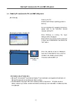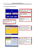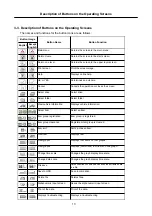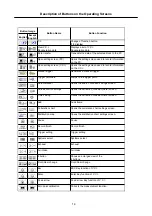
Harness Connection Procedures and Connection Order
6
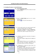
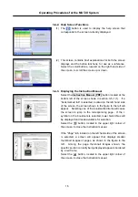
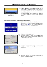
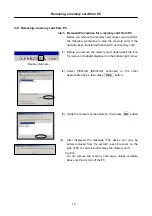
To perform diagnostics, first connect the cabling by following the procedures described below.
[1] Restart the PC.
[2] Connect one end of the USB cable to the V.C.I.
[3] Connect the other end of the USB cable to the PC.
[4] Connect the MUT-IIIharness to the V.C.I.
[5] Connect the MUT-IIIharness to the vehicle’s diagnostic connector.
* To disconnect the cabling, reverse the above procedures:
[6] Turn the V.C.I. power switch ON and check to ensure that the indicator lamp, located in the
upper right corner of the LCD screen, illuminates in green.
[7] Start up the MUT-III system software on the PC and turn the vehicle ignition switch ON to
begin performing diagnostics.
* If the version of the V.C.I. software installed in the PC is different from the version of the
firmware within the V.C.I. itself, then a V.C.I. software version upgrade will be initiated. If a
version upgrade error occurs, restart the V.C.I. while simultaneously depressing the
button on the V.C.I., in order to resume diagnostic testing.
1-4. Harness Connection Procedures and Connection Order
Open the lid covering the USB port,
which is located on the Right side of the
PC and indicated by the symbol.
Plug the USB connector into the port.
<Connecting the USB Cable to the PC>
[5]
[2]
[3]
[4]
[6]
[7]
[1]
<Connecting the Measuring Adapter and Probes>
Connect the Measuring Adapter to the V.C.I. trigger
port then connect the measuring probes to the
adapter, matching the color of each probe plug to
the appropriate color on the adapter jack.
Connect the trigger harness to the
trigger port of the V.C.I.
<Connecting the Trigger Harness>


