


Operating Procedures for Measurement Functions
63
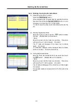
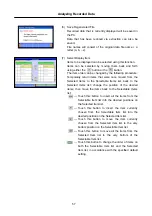
6-1. Operating Procedures for Measurement Functions
6-1-1. Measurement Function Menu
Select the
Special Function
button from the function
selection menu to enter special function mode.
Switch to the
Measurement Functions
menu, using the
tab located at the top of the screen.
<Note>
For the method used to connect the measuring probes,
refer to section "2-2-2. Measurement Functions".
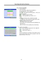
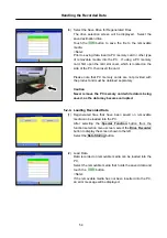
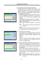
6-1-2. Voltmeter
Select the
Voltmeter
button from the menu screen shown
in section 6-1-1.
The voltage is read from the trigger port, by using the
measuring probes. The numeric values are displayed on
the PC screen.
Prior to measurement, perform zero point calibration by
touching the button while the probes are short-
circuited.
<Note>
DC voltages ranging from +/-40V can be measured.
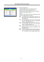
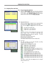
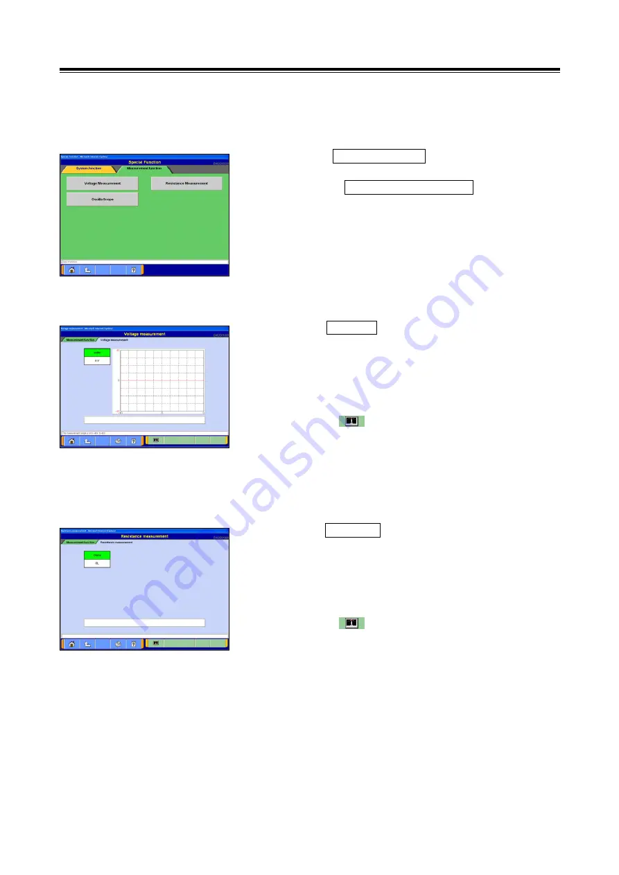
6-1-3. Ohmmeter
Select the
Ohmmeter
button from the menu screen shown
in section 6-1-1.
The resistance is read from the trigger port, by using the
measuring probes. The numeric values are displayed on
the PC screen.
Prior to measurement, perform zero point calibration by
touching the while the probes are short-circuited.
<Note>
Resistance values ranging from 0 ~ 100kOhm can be
measured.


