Operating Procedures for
V.C.I. Stand-alone Diagnosis
67
7-1-2. Reading Diagnostic Trouble Codes (DTCs)
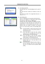
(1) Connect the V.C.I and the diagnosing vehicle with an
appropriate main harness (TYPE-B/TYPE-E) securely, turn
the V.C.I. power ON, and the V.C.I. LCD screen displays
the Main Menu as illustrated on the left.
Confirm that “
1. Read DTCs
” is displayed, then press
(Enter) button.
<Note>
•
If the V.C.I. is set on Drive Recorder mode, the LCD
displays Drive Recorder menu screen (refer to 5-1-1(16))
Please press (Esc)button twice in quick succession
to cancel the Drive recorder mode.
•
Necessary program/data for V.C.I. stand-alone diagnosis
has been transferred automatically into the memory card.
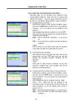
(2) System Select
Press button to browse the list until the LCD displays
the system you want to diagnose, then press (Enter)
button.
The display scrolls in the direction of the arrow displayed
on the first line. To switch the direction, press (Esc)
button once.
<Note>
If you press (Esc) button twice in quick succession, the
screen goes back to the Main Menu (1).
The scrollable last line is displayed as
「
##############
」
.
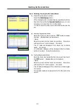
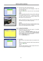
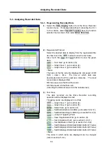
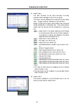
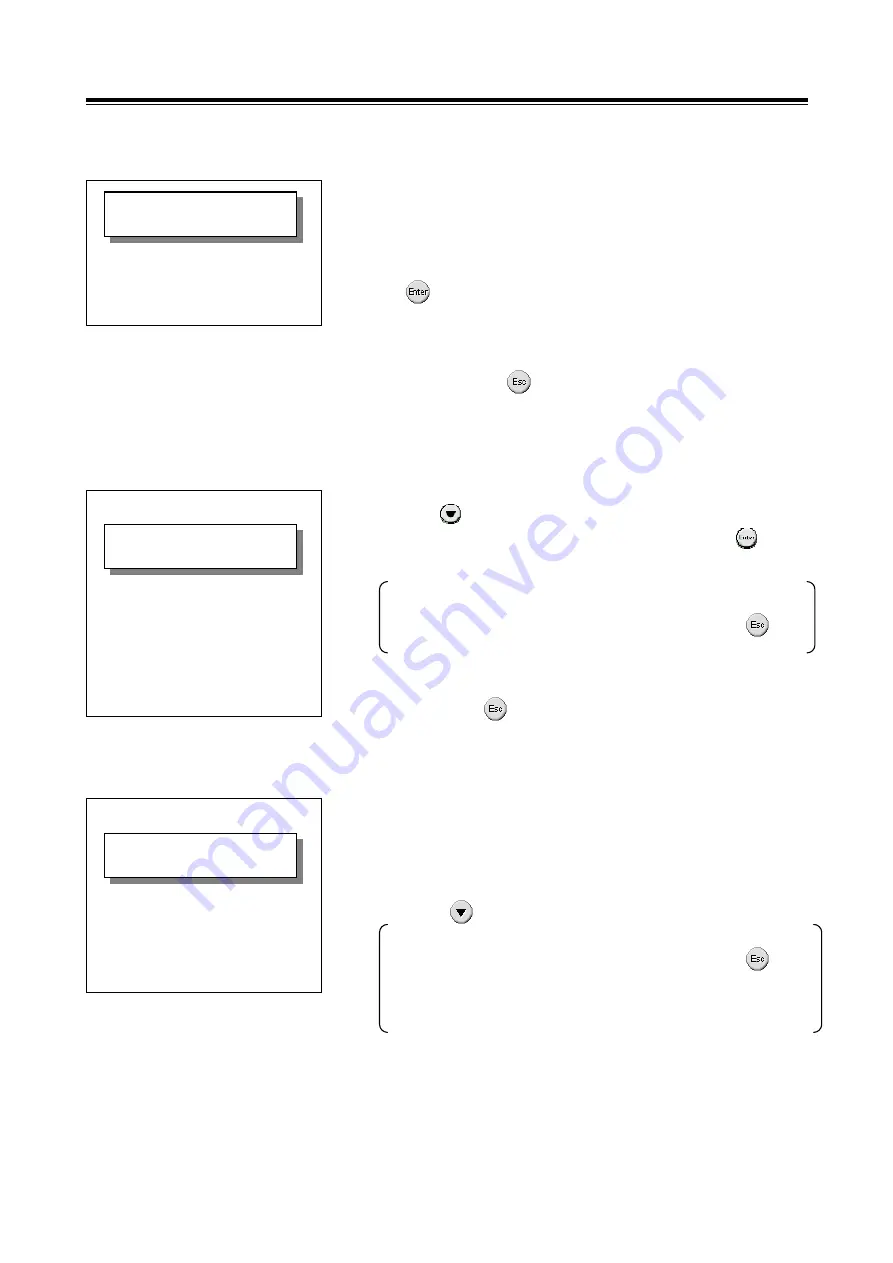
(3) DTCs Display
The DTCs that have been read from ECU are displayed.
•
The number shown on the right edge of first line is
indicating [The number of reading order / Total number of
detected DTCs].
•
Press button to display the next DTC.
The display scrolls in the direction of the arrow displayed
on the first line. To switch the direction, press (Esc)
button once. (When having only one DTC, the arrow is not
displayed on the first line.) To switch the direction, press
(Esc) button once.
<Main Menu>
1 Read
DTCs
2 Voltmeter
3 Ohmmeter
<DTCs>
↓
1/10
P2199# EGR Temp
P2413# EGR System
P0016# Ne SNSR O
P0607* ECU System
|
################
ex:
<System Select>
↓
ENGINE
TRANSMISSION
INTEGRATION CONT
ABS/ASR
AIR BAG
AIR CONDITIONER
IMMOBILIZER
################
ex:

