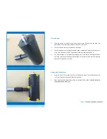
background image

16. Final Testing


 

Connect an adjustable power source to the DC Input of the inverter using a banana jack. 
The inverter and the automatic storm control stay activated. 


 

Supply  the  turbine  with  a  DC  voltage  of  5  V.  The  turbine  should  rotate  slowly  in 
clockwise  orientation  (Perspective:  Rotor  in  front  of  tower).  The  turbine  should  guide 
the rotor with the wind. 


 

Supply the turbine with a DC voltage of 25 V. The rotor should now rotate at high speed. 
The inverter should feed AC energy into the grid.  


The voltage should only be increased gradually. Do not connect a battery or any other power 
source to the turbine or inverter as these provide high  shock currents. This might loosen the 
screw fixing the rotor or damage the generator. 


THE INSTALLATION IS NOW COMPLETED.


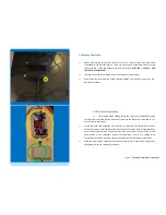
15. Installing The Blade


 

Activate the manual turbine stop 

or make sure that the storm control is without power. 

This way the turbine will not start up immediatly after installation of the rotor blade. 


 

Install the patented SkyWind rotor blade as the last part of the installation. The blade is 
made of one piece and ships balanced for best possible performance. After installation 
of the blade between the two precision made aluminum cones, the single fixing screw is 
tightened until the lock ring is pressed flat. This rotor fixing screw (red marking) must be 
fixed with a torque of 7 Nm. 


 

Cover  every  part  of  the  turbine  nacelle  and  mast  adaptor  with  a  protective  wax 

(delivered together with your turbine) after installation. For coastal sites with salty air 
this must be done inside the turbine nacelle (Fig. 5) as well. 


The turbine may now be started up for the first time and should work immediatly. The start up 
speed will decrease considerably within the first 100 hours of operation under load. 


Page 11 

| SkyWind Installation Handbook


Summary of Contents for SkyWind NG

Page 1: ...Micro Wind Turbine Rev 2 0 SkyWind NG Efficient Wind Power The installation must be done by trained professionals only The installer must be qualified and accredited for work on AC electrical installations Expert knowledge and documentation is mandatory ...

Page 2: ...d inverter with LCD Display 1x Grid connection cable for grid inverter 2x Dump load resistor connection cable 2x Dump load resistor wall mount 1x Dump load resistor Automatic storm control including 1x Wind speed sensor 1x Turbine cut out relais 1x Storm control unit Spray Can Protective Wax Coating All parts must be checked for any visual damage Only new and undamaged parts must be installed Only...

Page 3: ...ground at least BASIC RULE The closer a turbine is mounted to the ground the more energy of the airstream will be lost due to ground friction In most cases a turbine installed in 6m height will generate only 30 40 of a turbine mounted at 10m hub height at the same site When installed on a rooftop the hub height should be about 1 3 of the buildings height or width whatever is greater above the buil...

Page 4: ...o not place the turbine on the back This would lead to the metal deforming once the cover is removed Check the turbine for any potential visual damages Check the generator by turning the shaft by hand If needed you may conect the genera tor to a 30 V DC power source The generator should consume about 0 45 A Any visual damage on the turbines packaging must be reported to the shipper immedi atly upo...

Page 5: ...of loss of screws please contact FuSystems SkyWind 5 Nacelle Cable Connection Measure up 6 mm AWG 10 solar cable so that the lengh will be sufficient from turbine to the inverter The DC cable should not be longer than 20 m If a longer distance must be covered change from 6 mm to 12 mm AWG 6 after the first five meters The dis tance covered DC must not exceed 50 m in any case Lead the cable from th...

Page 6: ... of a voltage drop The switch may only be operated every five minutes to allow cool down of the relay Make the necessary DC connections between automatic storm control and inverter See wiring diagram on the next page for details 7 Mounting Preparation Attach a fitting ring terminal to the end of your DC cable to ensure easy and quick connection to the inverter later on If you use more than a singl...

Page 7: ...he turbines limitations The storm control will stop the turbine by short circuiting the turbines DC side For this reason the poles Nr 1 12 and 3 32 must be connected to each other The wind sensor must be installed 0 20m below the rotor discs lowest point on the mast of the wind turbine After installation the system must be checked in two separate ways 1 Shut off the turbines AC power The rotor rot...

Page 8: ...lack connectors la beled with DC INPUT yellow marking Make sure that the polarity is correct Mount the dumpload close to the inverter but not below it In case of too much power the resistor might become very hot Do not mount it onto flammable surfaces and use the mounts delivered with your turbine Connect the dumpload to the connectors labeled DUMPLOAD green marking Page 8 SkyWind Installation Han...

Page 9: ...t da ta field Activate the data set up by pushing the Gear button on the side of the display and select the cor rect number by again using the arrow buttons By pushing the Gear button again you confirm your ent ry Enter the complete power curve After completing the power curve navigate to the Dumpload box by using the arrow buttons and acti vate it using the Gear button Select 45V if you decided f...

Page 10: ...ng screws yellow markings Make sure that both screws are evenly tightened The nacelle must be fixed in an absolutly parallel position to the ground 13 Finalizing The Electrical Installation Check the whole electrical installation and write down your wiring diagram Document all settings of your storm control system and of your inverter by taking pic tures Without photographic documentation your war...

Page 11: ...the manual turbine stop or make sure that the storm control is without power This way the turbine will not start up immediatly after installation of the rotor blade Install the patented SkyWind rotor blade as the last part of the installation The blade is made of one piece and ships balanced for best possible performance After installation of the blade between the two precision made aluminum cones...

Page 12: ...orm as no wind turbine is able to withstand the ext reme forces of such events This document represents the interpretation of the original document Bedienungsanleitung Version 4 0 which may be found online at http myskywind com SkyWind Infothek Flyer Broschuren Vide Bedienungsanleitung SkyWind 4 0 pdf and was made to the best knowledge of the interpreter Only the original document is legally bindi...

Reviews:

Related manuals for SkyWind NG