6. Nacelle Finalization
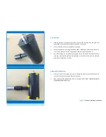
Mount the nacelle cover again using the screws marked in yellow. Fix the yellow screws
with 2 Nm torque.
During installation the turbines yaw
-
axis can be locked to make installation easier and
safer. This can be done by tightening the yaw
-
lock screw (red). Before the turbine can
begin operation this screw has to be loosened so that half its lengh is outside the turbi-
ne. After installation fix the screw using Loctite.
The bearing
-
lockers should be checked (green). If these are too tight the turbine won´t
be able to yaw correctly. If these are too loose the turbines operation might be louder
than expected.
Never use any other screws than those delivered with the turbine! In case of loss of
screws please contact FuSystems SkyWind.
5. Nacelle Cable Connection
Measure up 6 mm² (AWG 10) solar cable so that the lengh will be sufficient from turbine
to the inverter. The DC cable should not be longer than 20 m. If a longer distance must
be covered, change from 6 mm² to 12 mm² (AWG 6) after the first five meters. The dis-
tance covered DC must not exceed 50 m in any case.
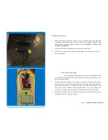
Lead the cable from the down end of the mast adaptor into the nacelle (see picture).
Please note that the generator must not be dismounted to do so.
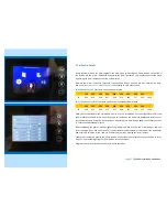
Lead one cable left to the generator, one cable to the right of the generator (see pic-
ture) towards the generators connection cables. Apply plenty of grease to the mast
adaptor.
Connect the generator cables to your DC cables using crimp connectors.
Fix the cables to the nacelle using zipties at the dedicated wholes in the nacelle (see
picture).
Page 5
| SkyWind Installation Handbook

